






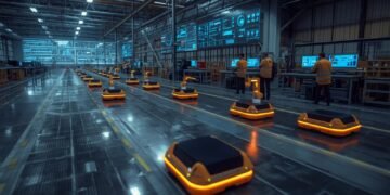






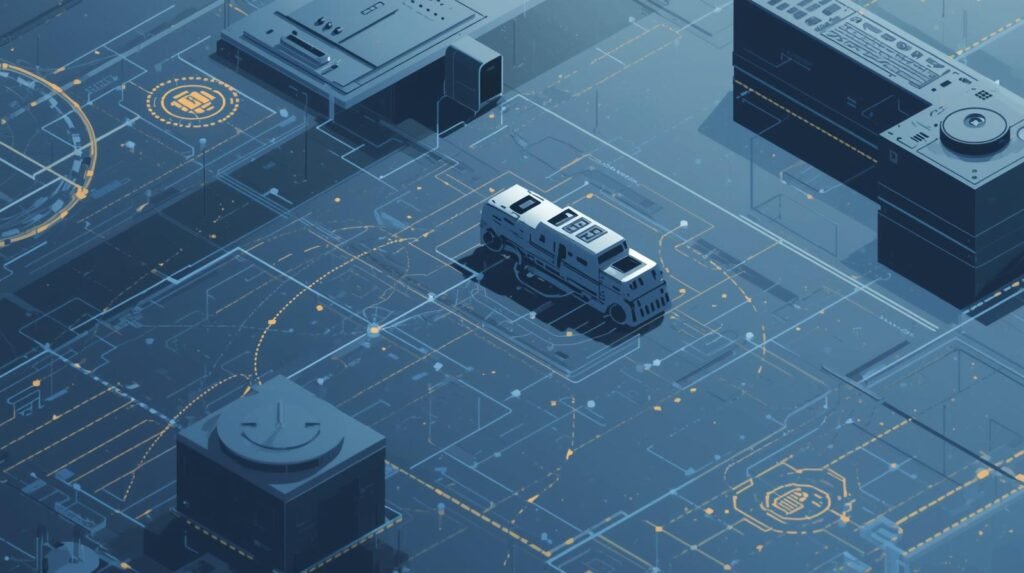
The most costly way to identify your own mistakes when they occur can cost you millions. A good example of this would be a company spending millions of dollars on a brand-new robotic arm. On its first day of operation, the robotic arm smashes through parts. The most significant lesson this company will have learned the “hard” way is the potential dangers of developing and designing extremely complicated, very difficult-to-correct machines (such as physical robots).
If the company had damaged that robot a thousand times prior to spending a single dollar or building the robot itself, then that’s exactly how robot simulation works. Robot Simulation is software that allows designers to create a digital model of their design and test it in a virtual world. This allows the designer to identify problems and find solutions before actually assembling and powering up the real robot. If we compare this to a flight simulator, a disastrous failure is merely a code error that needs to be corrected.
There are three primary reasons why robot simulation is essential. It can significantly reduce costs, protect both people and robots from damage, and enable large-scale testing that is necessary to train and refine robots.
#Digital Twin for Robots – Smart Essential Guide in 5 Steps
The fact that virtual testing of robots by designers has become a reality and the impetus for most of the advancements we are seeing today with regard to robotics is an example of how robotic simulation is being used as a way to control risks associated with robotics projects. Surgical robots used in hospitals, the Mars rover, and many other complex robots in use today were all tested in a simulated environment prior to deployment in the physical world.
Summary:
Robot Simulation Software is designed to assist in developing, testing, and refining robots in a simulated environment before actual hardware construction. Rather than relying on costly trial and error, teams can create models of robot arms, mobile robots, tools, sensors, and entire work cells to see how each element interacts and functions. This allows designers to confirm reach and clearances; determine potential collisions; estimate cycle times; and validate basic control logic, all without damaging equipment or causing safety-related incidents.
Robot Simulation Software can be applied throughout the entire robotic development process. Designers can develop detailed layouts and tooling designs. Programmers utilize simulation to test/debug path performance, optimize performance, and test for response scenarios (missing parts, delayed signals, etc.). Operations teams may simulate their cell to train employees and develop safe start-up/shut-down procedures.
In addition to the examples provided previously, many of the platforms available today offer “digital twin” capabilities. A digital twin can be a virtual model of the system that can guide upgrades and improvements after the initial deployment of the software.
The objective of this article is to explain what Robot Simulation Software is, explain what Robot Simulation Software can and cannot predict, and describe the benefits of utilizing Robot Simulation Software to provide faster commissioning, lower costs, and higher reliability to the automation of your business. The article will also include key characteristics to evaluate when selecting Robot Simulation Software and provide best practices to achieve accurate, repeatable results.
What Robot Simulation Actually Replaces (Reality vs Virtual Table)
| Real-World Task | Simulation Equivalent | Benefit |
|---|---|---|
| Testing robot movement | Virtual motion simulation | No physical damage risk |
| Training robot tasks | AI training in simulation | Faster learning cycles |
| Collision testing | Virtual obstacle scenarios | Prevents real-world accidents |
| Factory layout planning | Digital environment modeling | Qptimize workflows before setup |
| Robot programming | Code testing in the simulator | Debug without downtime |
Example: A robotic arm can be tested for collision errors virtually instead of damaging real equipment.
Source: ABB RobotStudio Simulation
https://new.abb.com/products/robotics/robotstudio
The Invisible Blueprint Behind Modern Robotics
Prior to now, the possibility of developing an advanced robot could have been viewed as impossible from either a financial standpoint or a mechanical standpoint. There were many large hurdles to overcome when creating massive robotics projects. These included the risk of expensive crashes or programming errors. Robot simulation provides the link necessary to create the technological advances needed to accomplish these huge leaps forward. In other words, a virtual environment where robots can try out new actions, fail at those attempts, and learn from them without having to pay the price in real life.
Robot simulation software is the unseen structural design of nearly every modern robot. The software serves as the digital dress rehearsal and the private training ground for the overwhelming majority of modern robots. It is the place where errors cost nothing, learning accelerates, and safety is perfected. This is why robot simulation is so important. It allows what is traditionally considered a high-risk gamble to be transformed into a highly practiced performance. What would normally take months of physical work can be accomplished in days using virtual testing.
The next time you see a video of a dancing robot or read about an automated warehouse, you’ll understand how important the “secret” ingredient was. The most important task they performed (and the thousands of hours they spent practicing) took place in that virtual world before they turned it on. You’re not just watching a machine. You’re watching the behind-the-scenes actions that make everything else possible.
What is Robot Simulation? Think of it as a Video Game for Robots
The core purpose of what robotic simulation software accomplishes is virtually identical to the type of gameplay you would find in a high-end video game. Rather than having someone use a controller to operate the robot, engineers program the instructions—the “code”—that tell the simulated robot exactly how to move, interact, and accomplish each specific task. The first way robots are simulated is as a virtual playground where engineers can teach the robot before it is manufactured.
In addition to the simulated robot, this digital world contains a total replica of the robot’s entire working area. Whether the working area is a hectic factory floor or a complex hospital environment, engineers can replicate it for the robot. The star of the simulated world is the robot’s “digital twin,” a 3-dimensional representation of the actual machine. The digital twin performs all functions in the same manner as a real-world machine. The digital twin moves, views its surroundings, and reacts to them in the same way that a real-world machine does.
In this simulated world, engineers can test their robot’s functionality. Engineers can continuously test and modify the programming of their robot to determine how it will behave. Additionally, engineers can test thousands of scenarios, many of which would be extremely difficult to replicate in a real-world setting. Is the robot capable of separating packages? Will the robot be able to navigate through a cluttered space? With each simulated testing scenario, the robot learns and becomes better at performing tasks — by learning from each experience, the robot becomes smarter and more reliable.
Robotic Simulation: Safely Explore Robot Behavior Without Physical Risk
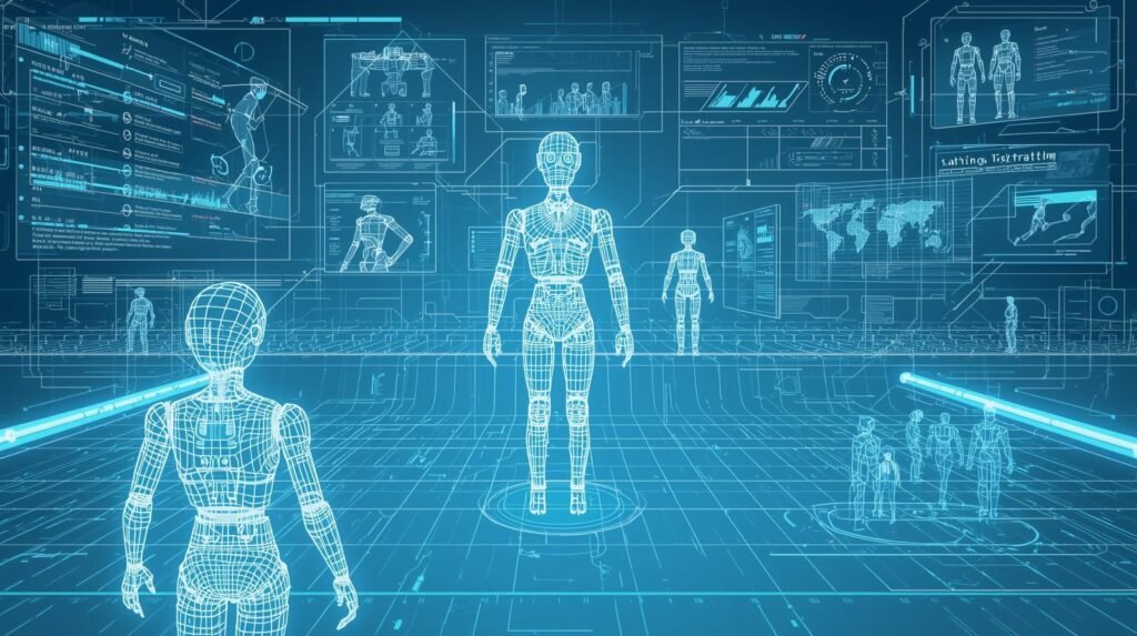
Robotic Simulation gives you the ability to see how a robot will perform in a variety of environments before physically building it. Using Robotic Simulation, you can develop a wide range of environments that would be difficult to replicate on a physical machine at a lower cost. The simulated environments include, but are not limited to: obstacles (such as people walking through the area), Low light levels, Slippery floors, crowded factory aisles Obstacles (such as people walking through the area), Low light levels, Slippery floors, Crowded aisles in factories, etc.
Robotic Simulation Software enables engineers to load CAD drawings of their robot, set limits for each joint, and use physics-based motion simulation to predict how the robot will move and whether it may collide with objects in the surrounding space or tip over from excessive torque. In addition to simulating motion and collisions, the same Robotic Simulation software can be used to visualize the robot’s movement by replaying previous trajectories, measuring cycle times, and evaluating the reachability of points in the workspace.
This data collected during simulation can help engineers optimize their tooling and layout prior to production. Novice operators and students can also use Robotic Simulation to study coordinate frames, path planning, and safety zones without fear of damaging equipment.
Safety is another key benefit of Robotic Simulation. Safety can be validated in Robotic Simulation, including validating emergency stop procedures, speed limiters, and cooperative behavior between robots and humans. It is also possible to simulate sensor-related failures (such as sensor noise and latency) to test how the control code will react to a loss of camera image quality, a lack of lidar return signal, or a slipping gripper. By testing these “what if” scenarios in Robotic Simulation, the chance of the first failure occurring on the shop floor can be reduced.
A Digital Twin of Your Cell – Not Just Engineering Design Support; Effective Communication. Using a digital twin of your cell to demonstrate how light curtains and guards work together to prevent motion and simulate throughput prior to ordering is just one way simulation can aid in communication. In addition, many robotic simulation platforms provide simulated data to test vision models and enable detection and grasping across multiple environments. Additionally, by using robot simulation software that supports version control and repeatable test scenarios, all model updates will be tracked similarly to how code changes are tracked in source control for software development.
Additionally, Robot Simulation is a great way to rapidly iterate. Unlike waiting for lab time, you can run many simulations at once (parallelizing), compare different controller types, and adjust parameters overnight. In addition to running simulations quickly, combining robot simulation software that supports scripting or ROS integration lets you leverage the same algorithms you will deploy, collect the output, and debug deterministically. Overall, utilizing robot simulation software to shorten commissioning time and continually improve performance will ultimately be beneficial.
To gain the greatest value from your robotic simulation efforts, it is crucial to build models that are as accurate as possible to represent your actual system: correct mass, friction, payload, and sensor locations. Start with a simple system and increase the complexity as your confidence grows. Finally, use robotic simulation as a decision-making tool, not as a guarantor; test those critical behaviors on physical equipment once virtual simulations have confirmed stability. If used correctly, robotic simulation software will be the safest path to improved performance, reduced unexpected failures, and reliable robotics – an efficient step toward faster and safer product launches.
Cost of Errors: Simulation vs No Simulation
| Scenario | Without Simulation | With Simulation |
|---|---|---|
| Robot collision | Equipment damage ($50k-$500K) | No cost (virtual test) |
| Production downtime | Days or weeks lost | Minimal disruption |
| Design flaws | Found late (expensive fixes) | Found early (cheap fixes) |
| Safety risks | High | Very low |
| Deployment delays | Common | Reduced significantly |
Statistic: Simulation can reduce robot deployment costs by up to 30%
Source: McKinsey Automation Insights
https://www.mckinsey.com/capabilities/operations/our-insights/automation-and-robotics
Creating a Safety Zone: How Robots Practice Dangerous Jobs in a Virtual World
Robot simulation offers numerous benefits for robot design engineers, supporting the safe development of robots that work near people in hospital or warehouse environments. Engineers can safely develop a robot to immediately move out of a human’s way when the human enters its path using a simulated test environment. This method provides additional protection for the robot and saves money on the robot’s surroundings. A malfunctioning industrial arm could potentially destroy the area around it; however, in a simulated environment, the robot can repeat the same task repeatedly without damaging itself or the surrounding area.
In addition to reducing risk, the main benefit of offline robot programming is that when the robot performs its first action in the real world, it executes perfectly because it was programmed in a simulated test environment. The simulated test environment is an ideal place to test for unexpected events, such as the robot’s emergency stop or an object in its path.
If an engineer fixes a problem in the simulated test environment, it means the robot will have a dependable, predictable “brain”. The proven code developed in the simulated test environment can be instantly uploaded to the physical robot, transforming the unknown robotic equipment into a reliable and trusted partner.
How Simulation Prevents Million-Dollar Mistakes and Project Delays
You’ll save money and time with the help of simulations. More importantly, however, you will create a safe working environment for both humans and robots that will eventually work together. Simulations allow you to test and validate your designs before any equipment is ever installed at the plant. When you create a safe working environment (as well as the opportunity to correct problems before the machines are installed) you will also lower the cost of production and the risk.
Simulations can serve as a “time machine” for testing. A physical robot or machine may only have so many hours per day for testing. A simulation of your machine or robot may be tested 24/7. With a simulation of your machine or robot, you could potentially simulate years’ worth of operational testing in only a couple of days. Because of this, the potential for testing a simulated version of your machine or robot is almost endless. Testing a physical version of your machine or robot has limits.
Virtual commissioning is such a powerful way to simulate your machine or robot that it has even been referred to as “virtual commissioning”. Virtually commissioning your plant is a complete full-scale dress rehearsal on the computer for your entire plant. Engineers can create simulated equipment models and test how they interact with each other before any real equipment is installed in your facility.
When you can find problems before they occur and test at an accelerated rate, simulation turns what was a high-risk enterprise into a science. Simulation does more than just reduce the risks associated with robotics and automation. Simulation also reduces overall implementation costs and enhances efficiency, product quality, and production speed.
#What Is a Digital Twin? 5 Powerful Ways Virtual Systems Create Smart Value
Robot Simulation Software: Test Robot Logic and Motion in Virtual Environments
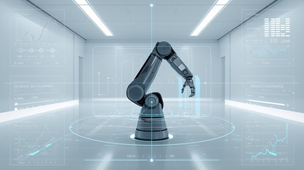
The use of Robot Simulation Software enables users to virtually design, develop, and test their robot’s motion and logic before physically implementing it. Instead of “discovering” how the robot performs by testing its capabilities on the manufacturing floor using trial and error methods, Robot Simulation Software allows users to create a digital work cell or “workspace”, set up the robot’s kinematics, and run simulation tests to see everything the robot will do.
The Robot Simulation Software enables development teams to validate the robot’s reach, confirm that there are no obstructions to tooling clearances, and identify potential collision areas before developing a program for the robot. The costs of repairing the robot and ensuring personnel safety are lower at this point.
In addition to verifying whether the robot program will “just run,” Robot Simulation Software also enables users to assess the overall quality of the robot’s motion. To accomplish this, users can review the robot’s planned paths, joint limits, accelerations, and singularities. Users can then modify waypoint locations and/or speed values to minimize vibration and maximize production cycle time. Many Robot Simulation Software packages have been developed to include built-in collision detection and clearance-checking functionality, which allows developers to discover near-collision scenarios that cannot be identified from a code-review standpoint.
Robot simulation software gives you the opportunity to check whether a robot is capable of handling parts without applying too much stress to the axis, and/or creating a potentially unstable motion with the correct payload and accurate CAD model.
In addition to checking for motion, it is important to verify a robot’s logic. Using Robot Simulation Software, developers can test their programs’ responses to simulated I/O signals, PLC handshakes, safety interlocks, and sensors under both normal and abnormal operating conditions. As such, users may simulate a “no part detected” condition, a delayed input signal from a conveyor, a jam, etc., to evaluate the robot program’s reaction and recovery to these events. Additionally, repeatedly simulating “what if” scenarios using Robot Simulation Software will reduce debugging time and make comparisons across versions easier.
Virtual environments will also enhance collaboration among the mechanical, control, and operational teams by allowing all teams to evaluate the same virtualized cell; therefore, they can collaborate and agree on station configurations prior to the installation of the robotic system. Many manufacturing organizations utilize robot simulation software to create a digital representation of the system, allowing operators to practice starting up, changing over, and safely shutting down production without affecting operations.
Finally, if your shop uses ROS (Robot Operating System) or scripting, Robot Simulation Software can be used in conjunction with automated testing to test each code modification against established operating conditions nightly.
A high-fidelity model of a robot system is required to obtain reliable simulation results. High-fidelity models result when the modeler ensures model fidelity (accuracy) and process discipline (a disciplined method for building the model). These goals are accomplished by using correct tool center points, friction/mass values representative of the robot or machine being modeled, and sensor placement that accurately replicates the physical machine configuration.
The most effective way to develop a high-fidelity model of an industrial robot system is to start with a basic configuration and incrementally add complexity until the core functional behavior is validated. Only after the model’s core functionality has been validated can multiple robots, vision guidance systems, and other components be incorporated into the simulation. Once you have developed a robust simulation model, use it as a powerful filter to quickly identify potential issues in your design.
Then, verify the performance of critical motion(s) using the same robot on real hardware under controlled conditions. Utilizing Robot Simulation software in this manner will enable safer commissioning of the robotic system, reduce unplanned/unexpected events during its integration, and facilitate its development.
Example
A food packaging firm has decided to create a new “pick-and-place” workstation for packaging snack boxes. Before purchasing the required tooling, the engineer uses Robot Simulation software to build the workstation, import the robotic model and gripper CAD drawings, and write a rough version of the cell’s programming. The initial run of the simulation reveals that there will be a collision if the arm rotates close enough to one or more of the guards (safeguards), and that the cycle will take about 0.7 seconds longer than desired.
By increasing the elevation of the conveyor belt, by changing the entry angle of the arm into position with the product, and by adjusting the maximum rate at which the acceleration limits can be reached during a portion of each cycle, the engineers were able to eliminate all collisions from occurring as well as meet their desired target cycle time. As such, they would only need to make some minor adjustments to the installed equipment.
Robotics Simulation Software: Simulate Robotic Systems Before Real-World Deployment

Development teams can test and develop their robotic systems using simulation software prior to shipping to production. One major benefit of this type of software is that you can create a simulated version of your entire cell before you purchase the hardware. Your engineers are also able to upload CAD files for your customers’ or company’s products and view how all of the components (such as the robot, grippers, sensors, and conveyors) interact with each other in a simulated environment.
The engineers can use the simulation to determine whether the robotic system will have sufficient reach, payload capacity, and work envelope to confirm that the design concept is viable. Using the simulation to validate the design concept will reduce rework, shorten the time to commission the product, and increase the safety of product releases.
Another major advantage of using robotics simulation software is risk reduction. In a virtual environment, you can run thousands of cycles, test extreme edge cases, and examine failure modes on equipment without causing damage. You can also test for potential collision points, pinch points, and unsafe approaches and make adjustments to the robotic system’s trajectory and interlocks to avoid these issues.
Many businesses use robotics simulation software to verify the validity of their safety logic before allowing personnel near robotic arms while they are operating. Businesses have used this type of simulation to evaluate emergency stops, speed-limiter devices, and restricted areas. With the combination of the robot simulation software capabilities (collision detection and physically based motion), testing has virtually become a viable, repeatable solution.
Robotics Simulation Software offers the same advantages for control and software development. This allows the developer to simulate how their robots would respond to actual operational conditions by simulating I/O events, PLC handshakes, and sensor triggers. In addition, the developer can simulate failure conditions, such as delayed receipt of parts or sensor signals, to ensure the system fails safely and recovers quickly.
In addition, Robotics Simulation Software allows developers to integrate with additional tools utilizing scripting or middleware to perform automated testing. Developers may compare the results of each test with previous versions of the program, thereby creating a continuous improvement cycle using simulation rather than a one-time validation.
Robotics Simulation Software provides many other advantages for stakeholders and users. Prior to the real-world deployment of the robot and its related layout, stakeholders will be able to review and approve a digital version of both. Users will be able to test changeover and recovery procedures using Robotics Simulation Software prior to deploying the machine, thereby reducing learning time and ensuring consistency.
The simulation will be representative of the robot’s capabilities only if the model is realistic and includes all physical attributes that affect its behavior, such as mass properties, tool center point location, friction, and sensor locations. As you gain experience and confidence, you should begin with simple models and add layers of complexity.
It is ideal to use both the Robotics Simulation Software and the Robot Simulation Software in a phased validation process, where the designer first validates the design virtually and then validates the most important elements physically in a controlled environment. When properly executed, a simulation will result in improved safety, increased availability, and fewer problems throughout the automation integration process.
Example
The students are creating an autonomous delivery robot for hospitals that can navigate hallways and use elevators. The group uses robotics simulation software to create a digital version of their floor layout, add simulated moving pedestrians, and simulate random noise in the lidar and cameras. The students run hundreds of simulations using the same parameters as the real world (e.g., blocked hallways, poor lighting) to evaluate how well the robot maps its environment, avoids obstacles, and docks at a location. In this process, a glitch in the simulation caused by reflective surfaces that were not detected by lidar sensors around glass doors was identified.
Software for Robots: Control, Simulate, and Optimize Robotic Systems
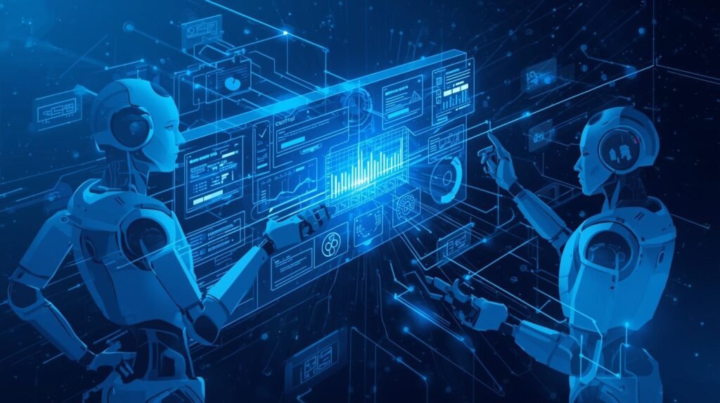
Robotics Software (robotics software layer) converts mechanical components into consistent, accurate systems that can detect their environment, decide how to respond, and execute appropriate actions. The overall framework of this encompasses all levels of robotic control, from low-level motor control to high-level task planning. Ultimately, the robotics software determines if a robot will be merely operational or truly useful.
Robotics software at the control level manages both the robot’s safety and motion profiles, as well as the coordination of its multiple axes. In addition, robotics software provides real-time feedback from encoders and sensors to ensure the robot’s accuracy under varying load conditions.
In more complex cell configurations, robotics software also interfaces with programmable logic controllers (PLCs), conveyor systems, and vision systems to enable coordinated action, signal exchange, and the enforcement of safe-state conditions.
Simulation is one of the fastest ways to verify these decisions prior to exposing the equipment to potential risk. Robot Simulation Software creates a digital version of the real world to test how far a robot can reach, detect potential collisions, and determine whether it can complete its cycle in a reasonable amount of time. Teams can use Robot Simulation Software to run “what-if” scenarios based on factors such as missed picks, sensor noise, part misalignment, and unplanned robot stops. If these scenarios are created in the simulation, the logic should respond appropriately. When using simulation, teams can greatly reduce their commissioning time and eliminate costly mistakes made on the production floor.
Optimization is another area in which software can assist. The software can review log data from the robot(s), identify areas where the robot(s) are experiencing inefficiency (bottlenecks), and provide recommendations to correct them through a smoother path, revised acceleration limits, or improved sequencing. Robot Simulation Software can aid in this process by enabling designers/engineers to visually compare different cell/tray configuration/layout options and the possible routes/trajectories the robots could follow in the cell/tray.
When the virtual model used in the Robot Simulation Software matches the physical model of the cell/tray, the Robot Simulation Software will also be able to provide estimates of the impact of changing the layout/configuration of the cell/tray on throughput before the team makes any physical changes to the fixtures or updates the programming for the robots.
The most practical way to implement this design is to create a digital version of the cell, test it to identify problems, and then build it. To begin with, make a digital copy of the tooling/payloads you are going to use, then use Robot Simulation Software to check that there is enough space/clearance to move freely around all areas of the payload/tooling for safety reasons.
Once you’ve installed the simulated cell, you can track its performance using the monitoring functions in the Software for Robots. Use these functions to track issues such as downtime, quality, and performance changes over time. Once you’ve identified a performance problem, go back to the Robot Simulation Software and use it to simulate any changes you plan on making before you make those changes or write new code for the robots.
In the end, the Software for Robots is a program with three parts: control, simulation, and optimization—one continuous process: show it virtually; run it safely; measure it accurately; and optimize it logically. In addition to the above, Robot Simulation Software is an important part of this process, as it saves money, reduces time-to-market, and mitigates the risks associated with testing different configurations of the cell, routes, and trajectories.
Example
An auto parts manufacturer employs an automated welding robot that interacts with a programmable logic controller (PLC), a safety sensor, and a quality inspection camera. Their software for robots is responsible for selecting recipes, defining tool offset parameters, and sequencing I/O in real time; i.e., clamp confirmed, weld enable, torch on, camera triggering, and error recovery. In the past, when a sensor would intermittently drop off, the robot would freeze in mid-cycle. The Controls Engineer modified the state machine to repeatedly attempt to confirm the clamp status, record sensor drop events, and enter a safe position after multiple failed confirmation attempts.
Are There Simulators for Everyone? A Quick Look at the Tools
Robot simulators can be just as varied in their applications as software on phones or computers. Photo editing is an analogy of this idea. There are advanced, complex programs for professionals, and very basic, inexpensive apps for regular people. Robotics simulations are developed using the same design concept: they are built for specific purposes and within budgetary constraints. Thus, whether you are a large corporation or an interested student, there is a way to begin developing.
The main categories of these varieties fall under two general headings
- Advanced Tools: Leading robotics and vehicle makers like Tesla, Boston Dynamics, and many of the top robotics/vehicle manufacturers in India use the best tools available to develop and build their complex robots and vehicles. The most important technologies these companies use include advanced simulation software for performance evaluation, high-performance motors or actuators, and AI/ML for navigation. Most robotics developers in India are also using a variety of free/open-source digital twin simulations, Python/MATLAB/C++ programming languages for R&D, and computer vision technology.
- Free/Open-Source (Student/Hobbyist/Researcher): Used by students, hobbyists, and researchers to gain experience with robotics and try out new concepts.
There is an enormous amount of free robot simulation software available for experimentation. Much of this software has been developed using open-source methods; that is, a global network of volunteer programmers has contributed to its development. Gazebo is a well-known open-source robotic simulator. Often used in conjunction with the Robot Operating System (ROS), Gazebo allows anyone to create and test a robot on their own computer. It is the blueprint for the future of robotics that no one can see.
Robot Simulation Tools: Powerful Tools for Designing and Testing Robots
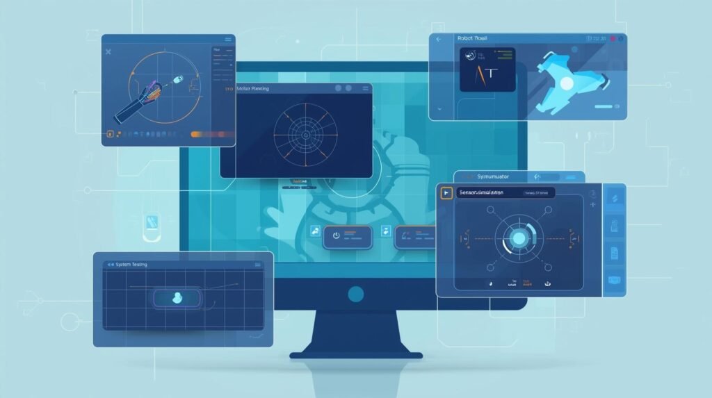
Using Robot Simulation Tools to create and evaluate robotic systems is extremely important. The appropriate Robot Simulation Tool allows a developer to create a digital work cell environment, enter CAD files, and test the performance of all equipment (robot arm, mobile robot, gripper, sensor, etc.) as they would be used. The benefits of creating and testing your design virtually greatly reduce the risk of physical injuries or damage during testing and allow your project to be completed much more quickly than with conventional methods.
The primary advantage of using Robot Simulation Tools is the ability to verify a design’s performance before manufacturing. A developer can evaluate the capability of their robotic system based on reach and accessibility. Also, it can be determined if there are any collisions between the robotic arm, fixtures, conveyors, safety zones, etc. Many of today’s Robot Simulation Tools also provide physics-based motion simulation, enabling developers to calculate cycle times, identify singularities, and check for potential joint-limit issues.
When a developer chooses a Robot Simulation Tool that accurately models the payload and inertia of their robotic system, the simulated system’s motion will closely resemble the real system’s.
In addition to verifying that all parts of a robot system work properly from a geometric perspective, Robot Simulation Tools help verify the underlying logic. By simulating input/output signals, sensor triggers, and PLC handshakes, developers can test their robot programs’ responses to a variety of production events. As such, many developers rely on Robot Simulation Tools to test “what if” scenarios (e.g., a missing component, a late-running conveyor, or failed inspection) to see how the system will break down and recover. Simulations in this fashion provide excellent tools for debugging, testing changes, and training, because they allow developers to quickly replicate the same test.
Robot simulation tools enable low-cost experiments to optimize robotic systems. Users can experiment with alternative pathways, robot locations, and tooling designs by using simulation tools without having to build each alternative. With the ability to fine-tune robot speed, smoothness, and sequence to minimize idle time while maintaining safe, stable motion, robot simulation tools can be used to design an optimal robotic system.
Models of digital twin workflows enable the virtual representation of a physical system (e.g., a robotic cell) to synchronize continuously with the actual system to support continuous improvement. High-quality models are needed to realize maximum benefit from robot simulation applications. That means you have to accurately represent the tool center points for each tool you plan on simulating. Use real friction coefficients whenever you are simulating processes that involve friction. Be sure to use accurate mass property data when simulating your robots and all other equipment. And position your sensors in the same locations as they would be in a real-world environment.
Select a robot simulation program that has the most appropriate features for your particular environment (industrial programming needs, ROS interface, etc.). Create standard testing procedures. Used properly, robot simulation applications can make the design and development of robotic systems a formalized, measurable process. Ultimately, it enables development teams to build better systems and reduces the number of “surprises” during deployment.
Example
A systems integrator is creating a quote for a multi-robot palletization system for a distribution center. Using Robot Simulation Tools (RST), he has compared two options for the robotic arrangement: robots placed side by side or staggered with a single in-feed conveyor. RST created Reach Maps, identified Interference Zones, and generated Estimated Throughput based upon various Box Sizes.
The Staggered Option appears to be faster in simulation, yet results in nearly constant near-collisions when both robots attempt to pick at the same time. Therefore, the Systems Integrator selected the safer of the two options (the Staggered Option), adjusted pallet locations, and produced an animation that was provided to the customer for approval. The end result reduced Commission Time and increased Operator Confidence
Popular Robot Simulation Tools Comparison
| Tool | Best For | Key Feature |
|---|---|---|
| Gazebo | ROS-based robotics | Realistic physics simulation |
| Webots | Education & research | Easy-to-use interface |
| NVIDIA Isaac Sim | AI robotics | GPU-accelerated simulation |
| ABB RobotStudio | Industrial robots | Factory simulation |
| CoppeliaSim (V-REP) | General robotics | Flexible scripting |
Example: NVIDIA Isaac Sim is used to train AI-Powered robots in virtual environments before deployment.
Source: NVIDIA Isaac Sim
https://developer.nvidia.com/isaac-sim
Robot Design Software: Design, Model, and Refine Robots Digitally
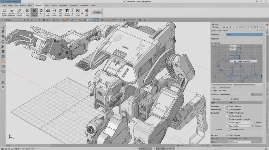
The primary advantage of Robot Design Software is that it allows engineers to design the mechanical aspects of their robot, model and test them digitally before creating prototypes by cutting metal or purchasing parts. Robot Design Software is the first step in the robotic development process. Using Robot Design Software, engineers can determine the overall mechanical design of the robot, define the geometric shape of each joint and link, and quickly compare numerous design concepts. Additionally, using Robot Design Software enables quicker iterative design, reduced prototyping costs, and better collaboration among multiple engineering disciplines (Mechanical, Electrical, and Control).
From a practical standpoint, the most efficient workflow begins by using Robot Design Software to define the robot’s geometry and configuration. Engineers will begin defining frames, arms, end effectors, and mounting plates within Robot Design Software. Engineers will also validate the clearance and access for performing maintenance within Robot Design Software.
Additionally, Robot Design Software is a good way to document important parameters such as link length, joint limits, and tool center point to ensure consistent information throughout the remaining phases of development. After validation, the design engineers may use the output from Robot Design Software, combined with the output from Robot Simulation Software, to assess how the robot performs under motion, acceleration, and interaction with the surrounding environment.
Many problems are found during the simulation phase. Collision detection, reachability of all desired points, position/ singularity related potential problems with the robot build process and robot motion are among the possible problems that may be determined by Robot Simulation Software.
Robot Simulation Software may also be used to test different gripper designs, fixture locations, and approach angles to optimize the robotic system’s cycle time and enhance its reliability. If the output mass properties and inertia values from the Robot Design Software are accurately calculated, the results from the Robot Simulation Software will be more representative of the robotic system’s real-world performance.
The use of Robot Design Software allows the engineer to refine the robot’s design based on payload, stiffness, repeatability, and safety requirements. The engineer has options available to increase the size of the links, move the motor to a different location, and/or alter the gearing. The engineer can verify whether these changes result in an improved design.
Robot Simulation Software is another layer of verification for determining whether the developed motion profiles will remain within established joint torque limits and how the robot will perform under extreme conditions (e.g., tight tolerances, sudden stops). Together, Robot Design Software and Robot Simulation Software enable the engineering team to develop a design that is both manufacturable and deployable.
The use of Robot Design Software, in addition to its engineering advantages, can also help improve communication. The development of a solid digital model allows all relevant parties to view it and collaborate on the conceptualization, cell layout, and preparation of assembly instructions. On the other hand, Robot Simulation Software can help create graphical representations of training or process approvals, reducing the risk of unpleasant surprises during commissioning.
It is therefore very important to keep all of your Robot Design Software and Robot Simulation Software as consistent as possible by maintaining the same coordinate frame(s), realistic limits for each joint, and the same tracking revision(s). By developing good practices for your Robot Design Software and establishing repeatable testing procedures using your Robot Simulation Software, you will be able to design and build robots much more quickly, make decisions much earlier, and have the confidence to continue developing and improving your robotic designs.
What Is a ‘Digital Twin’? Your Robot’s Perfect Virtual Copy
A Digital Twin for robotic automation is an exact digital replica of your physical robot (including all component details) that resides solely in the digital world. This digital replica will exist only in the digital world and mimic your robot’s movements.
Simulation software will allow you to build a digital model of the robotic arm’s physics, along with the motion of each joint. Simulation software helps you understand how the robotic arm and its joints move. Additionally, simulation software will help you understand the various components of the robot (such as motor speed and the weight of each part) and how they interact. When combined, this information allows you to test your robot under different conditions (i.e., lift large objects without damaging them).
The use of simulation greatly increases the accuracy of identifying any issues that may arise from a specific operation. For instance, simulation software could indicate that a particular movement would result in rapid arm rotation or that a collision with another object would occur. These issues could then be addressed before the robot was even constructed.
Therefore, when a problem is identified during testing, engineers will not have to make any modifications to the robot after it has been manufactured. Any solutions found through simulation can be integrated into the robot’s design at any point prior to manufacture, thereby ensuring that the final product will function correctly.
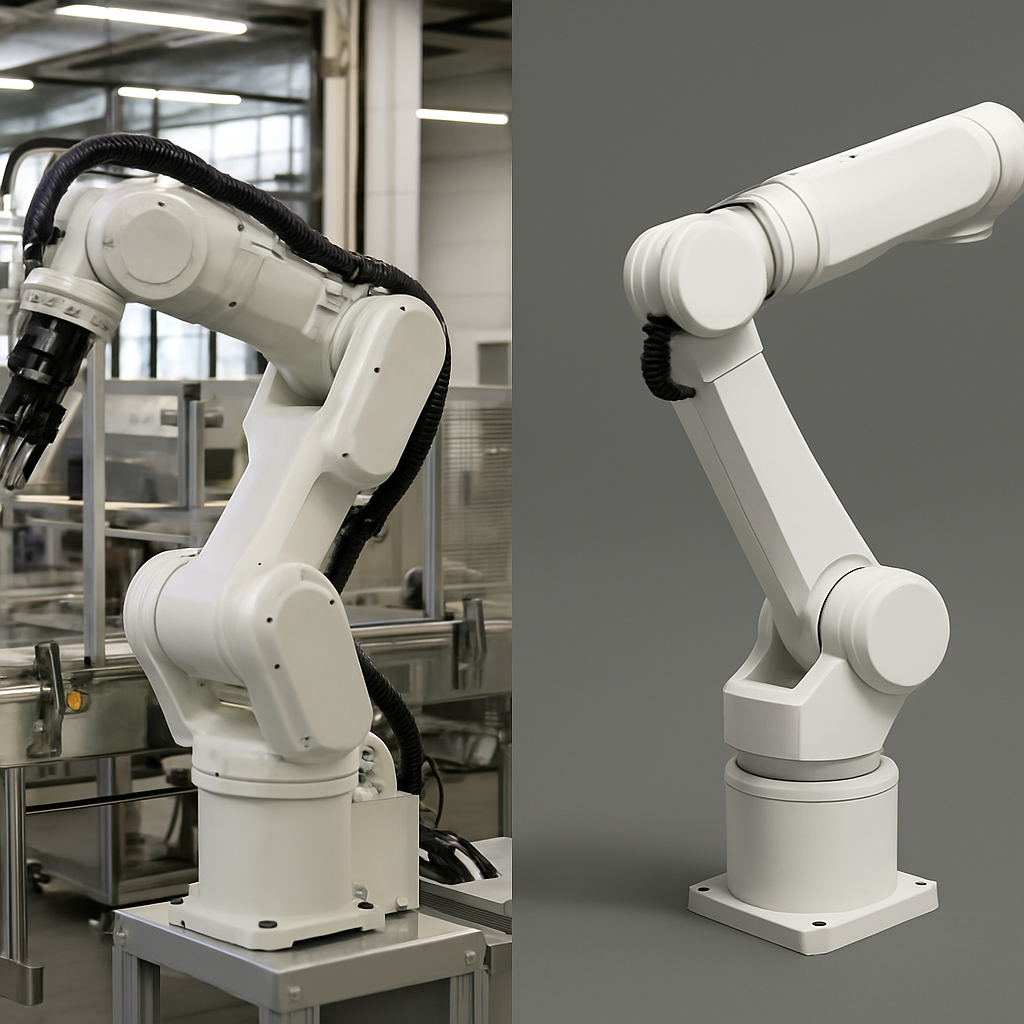
From Virtual Practice to Real-World Action: Making the Jump from Screen to Factory Floor
The benefits of simulated training mean little if it cannot be applied to actual robotic use. So, how does the simulation provide a robotic “perfect” performance and apply it to the world? Fortunately, it is easier than you might think. The perfect brain in the simulation (i.e., the specific code the robot uses each time it has to move or lift) can be copied directly and transferred to the physical robot. This would be like creating a song on your computer and then transferring the finished file to a speaker to play it. The work performed in the simulation will act as the physical robot’s own “instruction manual”.
The ability to transfer code to a physical robot is known as offline robot programming. The “off-line” part of this terminology refers to the revolutionary aspect of this method. Off-line robot programming means that the same group of engineers who develop and test a new task for a robot does not need the robot to be physically present while they are doing so.
In the past, programmers had to shut down the expensive machinery (e.g., assembly lines) so engineers could manually and slowly teach a robot its new task. Today, with advanced technologies, the same group of engineers can complete the same task on a different computer while the rest of the factory operates without interruption.
Offline robot programming provides several advantages. One advantage is that a robot on an assembly line currently performing packaging could have a programmer/developer working on the next program to simulate its future task (pallet stacking), while the robot continues to run. The moment the new program is developed and tested in the simulation, it can be transferred to the robot during a short break. Since the robot will never be idle for extended periods due to insufficient programming, assembly line productivity will be at peak levels. The ease of transitioning from simulation to real-world applications will enable robots to reach their ultimate level of speed, safety, and cost-effectiveness.
Simulation – Real-World Transfer (Sim-to-Real Gap Table)
| Step | Simulation Stage | Real-World Impact |
|---|---|---|
| Model training | AI learns in virtual world | Faster deployment |
| Environment testing | Simulate different conditions | Better adaptability |
| Performance tuning | Optimize robot behavior | Higher efficiency |
| Validation | Test edge cases | Fewer real-world errors |
| Deployment | Transfer model to robot | Ready for producation |
Example: Self-driving car AI is trained using millions of simulated miles before real road testing.
Source: Waymo simulation Research
https://waymo.com/research
Where is Simulation Used? From Exploring Mars to Your Living Room
The scope of simulation has extended far beyond manufacturing into the realm of outer space travel and the home. Simulation has also been applied in many ways to all types of robots. It provides the opportunity to test hypotheses and resolve problems at a lower cost and greater safety than in the “real world.”
One of the most significant examples of NASA’s use of simulation is its use on the Mars rovers. Because it takes approximately 20 minutes to send a command from Earth to Mars and receive a response, NASA engineers developed an extremely accurate digital model of the rover and the Martian surface. Engineers then simulate every possible action the rover could take, so they do not have to worry about the rover becoming stuck or tipping over when they give it a command, since it is far away from them.
Many automobile manufacturers also make extensive use of simulation technologies to design and develop their production systems, including simulating the motion and coordination of multiple robotic arms to perform functions such as welding, painting, and vehicle assembly.
At a much smaller scale, the manufacturer of your robot vacuum used simulation technology to program the robot to navigate thousands of virtual living rooms, avoiding obstacles such as chair legs and electrical cords, before developing the first physical prototype.
Therefore, simulation is a “what-if” sandbox for the next generation of modern robotics. It is a fundamental tool for both large and small corporations. Consequently, you might be wondering if this type of technology is only available to large companies or if individuals can start using simulation-based technologies.
Where Robot Simulation is Used (Application Spectrum Table)
| Domain | Simulation Use | Outcome |
|---|---|---|
| Space exploration | Mars rover testing | Safe mission planning |
| Manufacturing | Robot assembly simulation | Increased efficiency |
| Healthcare | Surgical robot simulation | Better precision |
| Gaming & VR | Physics-based interactions | Realistics environments |
| Smart homes | Home robot training | Improved automation |
Statistic: NASA uses extensive simulations to test space robotics before missions, significantly reducing mission risk.
Source: NASA Robotics Simulation
https://www.nasa.gov/robotics
My Observation
A unique angle for this article is to frame Robot Simulation Software as a “flight simulator for robotics decisions”—not just a 3D preview tool. Build the story around a simple, repeatable workflow called Simulate → Stress-Test → Sign-Off, showing how teams move from “it works in a demo” to “it’s ready for real production.”
- Simulate (prove the basics): create a digital cell, import CAD, define TCPs, and run the first safe path to validate reach, collisions, and cycle time.
- Stress-Test (break it on purpose): introduce controlled failures—sensor noise, timing delays, slippery surfaces, dropped parts, random offsets, emergency stops—and measure how the robot logic recovers. This turns simulation into a reliability lab, not a marketing animation.
- Sign-Off (make results actionable): use a checklist of pass/fail metrics (clearance margins, max torque, time-to-recover, safety zone compliance) and save scenarios as “tests” so every future code change is automatically re-validated.
This idea keeps the article practical and memorable, highlights real value beyond visuals, and naturally explains key features (physics, I/O simulation, digital twins, repeatability) while giving readers a process they can copy immediately.
Conclusion
The advent of virtual testing capabilities for engineering teams via robot simulation software has revolutionized how modern robots are both designed and delivered. By allowing engineers to test new concepts, motions, and control algorithms on a virtual machine, engineering teams can quickly and safely validate new machines before they interact with a physical machine. These types of simulations allow engineers to demonstrate robotic motion, reach, collision detection, cycle time, and control logic in a simulated environment. Additionally, simulation allows engineers to identify and correct potential problems before they cause hardware damage, halt production, or pose safety risks in the manufacturing area.
Simulation also offers numerous benefits at each stage of the project. For example, designers can refine their designs to include idealized tooling and layouts. Programmers can confirm whether input/output signals will function properly and determine failure modes. Lastly, managers can estimate throughput and timelines with increased accuracy. As digital twin workflows, synthetic data generation, and AI-driven development processes continue to advance, simulation is becoming a core component of continuous improvement — not just a pre-production validation process.
To maximize the effectiveness of robot simulation software, users need to create accurate models of payloads, friction, sensor output, and joint limits. Users should also run repeatable simulations and view simulation results as guidelines rather than definitive indicators of actual performance. Ultimately, when utilized appropriately, robot simulation software allows robotics teams to transition from concept to commissioning far more quickly. It also eliminates the possibility of unanticipated events. It improves the reliability of the systems. And it enables the creation of safer, more reliable systems that operate exactly as intended under real-world conditions.
FAQ’s
- Q. What does robot simulation software do?
A. The primary use of Robot Simulation Software is to create simulated environments in which you can build models of robots, tools, and work cells to test how they will move, perform logical functions, and perform before installing the real equipment. - Q. Why should I use robot simulation before I deploy it?
A. Simulation will allow you to avoid many of the safety and cost issues that occur when using robotic equipment, including collision, reaching issues, timing issues, and logic issues that could cause safety issues, downtime, and rework costs that result from making changes to the equipment after it has been installed. - Q. What can robot simulation software test and determine?
A. Possible areas where you may want to simulate include: reachability, collision/clearance, cycle time, joint limits, trajectory, sensor behavior, and basic I/O or process sequence (dependent upon the software being used). - Q. How accurately do simulation results match real-world robots?
A. The accuracy of the simulation results depends on the quality of the payload model, friction, inertial data, calibration (TCP, Frames), and similarity of the virtual cell to the actual cell. However, critical behaviors will always need to be tested in a real-world setting. - Q. What should I be looking at when selecting robot simulation software?
A. Some of the features that should be available when selecting a robot simulation tool include: ability to import CAD files, realistic physics, collision detection, support for most robot manufacturers, programming flow, integration with other systems (such as PLC, ROS), and a robust set of debugging and visualization tools.

Garikapati Bullivenkaiah is a seasoned entrepreneur with a rich multidisciplinary academic foundation—including LL.B., LL.M., M.A., and M.B.A. degrees—that uniquely blend legal insight, managerial acumen, and sociocultural understanding. Driven by vision and integrity, he leads his own enterprise with a strategic mindset informed by rigorous legal training and advanced business education. His strong analytical skills, honed through legal and management disciplines, empower him to navigate complex challenges, mitigate risks, and foster growth in diverse sectors. Committed to delivering value, Garikapati’s entrepreneurial journey is characterized by innovative approaches, ethical leadership, and the ability to convert cross-domain knowledge into practical, client-focused solutions.