











Executive Summary
Collaborative Robots are commercially useful when a production process needs automation but cannot economically justify a rigid, permanently isolated robot cell.
The opportunity is not simply putting a smaller robotic arm beside an employee. The real engineering problem is designing a complete application—robot, tooling, workpiece, safety functions, fixtures, software and human workflow—that can achieve the required throughput without exposing people to unacceptable risk.
That distinction corrects one of the biggest weaknesses in conventional cobot marketing.
A robot marketed as “collaborative” does not automatically make its application safe. ISO 10218-2:2025 treats robot safety as an application and integration problem covering design, commissioning, operation, maintenance and decommissioning; ISO/TS 15066 supplements the industrial robot standards with requirements for collaborative systems and their work environments.
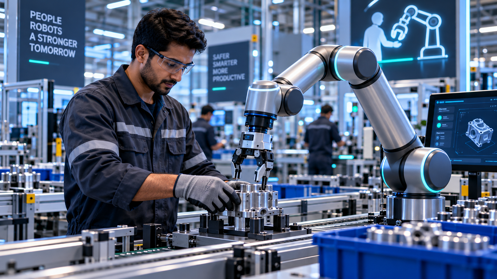
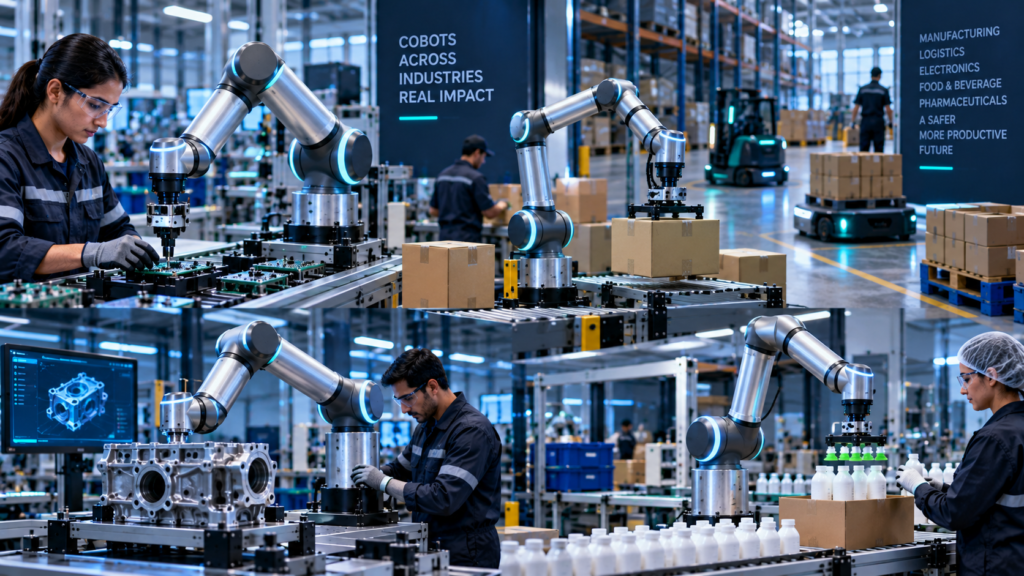
Common applications include machine tending, assembly, packaging and inspection. Each requires task-specific risk assessment, suitable end-of-arm tooling and a predictable operator workflow
The enterprise question is not:
“Should we buy a cobot?”
It is:
“Can this specific human-robot application achieve our cycle-time, quality and flexibility requirements after every credible hazard, integration dependency and lifecycle cost is included?”
Our operating model is:
SELECT → ENGINEER → ASSESS → INTEGRATE → VALIDATE → OPERATE → MEASURE → REDEPLOY
The procurement principle is equally simple:
Buy the application that delivers the lowest cost per verified good unit within the required safety envelope—not the robotic arm with the most attractive demonstration.
I. THE CURRENT MARKET LANDSCAPE & CHALLENGE
Collaborative Robots Have Moved Beyond the Lightweight-Cobot Stereotype
The old assumption was straightforward.
Industrial robots were large, fast and fenced. Cobots were small, slow and lightweight.
That boundary is becoming less useful.
Universal Robots currently specifies the UR20 at a 20 kg nominal payload, 25 kg extended payload, 1,750 mm reach and maximum TCP speed of 5 m/s. FANUC’s CRX/30-18A reaches 30 kg payload and 1,756 mm reach, while ABB’s GoFa family extends to 14 kg payload.
Those specifications do not mean those speeds or payloads are safe during close human collaboration.
They demonstrate why procurement can no longer use “small robot = cobot = safe” as its mental model.
The Market Is Material—but Traditional Robots Still Dominate
The International Federation of Robotics reported that cobots represented 10.5% of industrial robots installed worldwide in 2023. IFR’s 2025 report separately recorded 542,000 total industrial robot installations during 2024.
That is commercially meaningful adoption.
It is not evidence that Collaborative Robots are replacing conventional industrial automation.
IFR explicitly notes that cobots complement rather than replace traditional industrial robots, which retain an important productivity advantage where high-speed operation can be isolated from workers.
That is the first procurement lesson.
Sometimes the correct cobot is an industrial robot behind guarding.
The Real Automation Problem Is Process Variability
A traditional automated cell performs exceptionally well when:
part geometry is stable
cycle time is predictable
fixtures are controlled
product mix changes slowly
human entry can be minimized
production volume justifies dedicated engineering
Many small and mid-sized manufacturers face the opposite conditions.
They run short batches.
Operators change fixtures.
Components arrive with tolerances.
Product priorities change during the shift.
The business problem is therefore not merely labor substitution.
It is economically automating variability.
Why Cobots for Small Businesses Are Useful
Human-Robot Collaboration Works Best When Work Is Divided Intelligently
That principle survives technical scrutiny.
Robots are strong at repeatable trajectories, controlled dispensing, predictable handling and consistent machine interaction.
People remain useful for ambiguous defects, unexpected part conditions, rapid improvisation, changeovers and contextual judgment.
The best Human-Robot Collaboration workflow therefore does not ask:
Which worker can we replace?
It asks:
Which task elements should be deterministic, and which should remain adaptive?
Cost of Inaction Is Process Friction
A manufacturer that leaves an automation candidate entirely manual may incur costs through:
repetitive handling
unplanned absenteeism
ergonomic exposure
cycle-time variation
quality variation
overtime
rework
scrap
machine idle time
recruitment pressure
capacity constraints
But leaving a process manual is not automatically expensive.
Some tasks are too variable, too infrequent or too inexpensive to automate economically.
Cost of Inaction Formula
A NezzHub analytical framework is:
Manual Process Friction = Direct Labor + Overtime + Rework + Scrap + Ergonomic Exposure + Machine Idle Cost + Lost Capacity + Training/Turnover Cost
Now compare that against:
Cobot Lifecycle Cost = Robot + EOAT + Vision + Fixtures + Safety + Integration + Software + Training + Maintenance + Changeover + Downtime
The investment case begins only after both sides are measured.
The Most Dangerous Cobot Myth: “No Fence Means Safe”
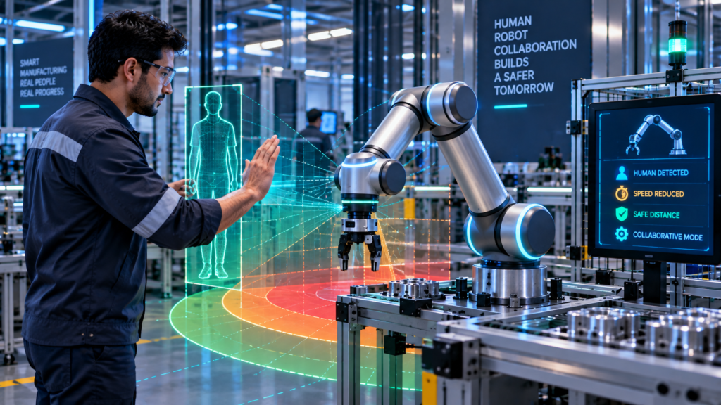
Fenceless operation requires an application-specific safety assessment. Tooling, workpieces, pinch points and operating conditions can create hazards even when the robot arm has collaborative safety functions.
ISO/TS 15066 addresses the collaborative robot system and work environment, not merely the robot manipulator.
Consider a power-and-force-limited arm carrying:
a sharp metal blank,
a welding torch,
a rotating cutter,
a hot component,
or an unstable 20 kg load.
The arm’s collaborative capability does not neutralize those hazards.
Cobot Safety is application safety.
II. DEEP-DIVE TECHNICAL ANALYSIS & EVIDENCE
Collaborative Robots Architecture: Eight Layers Between a Robot Arm and a Productive Workcell
A commercial cobot deployment is not one machine.
It is a production system.

Layer 1 — Business Task
Define the transaction first.
Examples:
load CNC machine
drive six screws
dispense adhesive
inspect weld
pack finished unit
palletize carton
“Automate assembly” is too vague.
Layer 2 — Robot Manipulator
Now select payload, reach, repeatability, mounting position, environmental rating and required motion performance.
Payload must include more than the workpiece.
Use:
Required Payload = Workpiece + EOAT + Sensors + Adapters + Cables/Allowances
Selecting the arm before calculating this stack is a common integration error.
Layer 3 — End-of-Arm Tooling
The robot’s value appears at the tool center point.
EOAT may include:
parallel grippers
vacuum grippers
screwdrivers
dispensing heads
force/torque sensors
welding equipment
sanders
inspection cameras
Layer 4 — Perception and Process Sensing
A deterministic fixture may need little vision.
A bin-picking application may require cameras, lighting, calibration and inference software.
Other processes need:
presence sensors
force sensing
barcode readers
torque feedback
part verification
machine state signals
Adding perception increases flexibility.
It also adds calibration and failure modes.
Layer 5 — Safety Functions
The application may use combinations of:
power and force limiting
speed and separation monitoring
safety-rated monitored stop
hand guiding
emergency stop
safe speed/position functions
The correct mode follows the risk assessment.
It should not be chosen because a sales demonstration looked convenient.
Layer 6 — Cell Integration
The cobot must communicate with the surrounding process.
That may include:
PLC
CNC
MES
SCADA
vision controller
safety PLC
conveyor
tool controller
warehouse software
quality system
A robot that moves perfectly but cannot synchronize with the machine is not an automated process.
Layer 7 — Human Interaction
The operator needs predictable behavior.
That includes:
clear status
obvious restart conditions
safe handoff
understandable alarms
accessible stops
controlled recovery
changeover instructions
Human-Robot Collaboration fails when operators cannot predict what the machine will do next.
Layer 8 — Production Verification
Finally, prove the transaction completed correctly.
Verify:
part loaded
screw torque accepted
dispense completed
inspection passed
machine cycle started
finished part removed
package complete
A motion-complete signal is not necessarily a business-complete signal.
Architecture Overview
The complete architecture is:
ERP / MES / PRODUCTION ORDER
↓
WORKCELL CONTROLLER
↓
ROBOT PROGRAM / TASK LOGIC
↓
PERCEPTION + PROCESS SENSING
↓
MOTION PLANNING
↓
SAFETY FUNCTIONS
↓
ROBOT + EOAT
↓
PART / MACHINE / FIXTURE
↓
QUALITY VERIFICATION
↓
PRODUCTION RECORD
↓
OPERATOR EXCEPTION HANDLING
This architecture explains why the robotic arm may represent only part of project cost.
Integration Flowchart: What Happens During One Cobot Cycle
PRODUCTION REQUEST
↓
Confirm correct recipe
↓
Confirm fixture and tooling
↓
Safety state valid?
No → inhibit motion
Yes → continue
↓
Detect or receive part
↓
Part condition valid?
No → operator exception
Yes → continue
↓
Plan / execute robot motion
↓
Perform process operation
↓
Read process feedback
↓
Quality condition passed?
No → rework / reject / human review
Yes → continue
↓
Release completed part
↓
Record production transaction
↓
Return to safe ready state
That is Cobot Automation.
The robot movement is only one step.
Collaborative Robots Need a Safety Envelope, Not a Safety Label
Define:
Collaborative Operating Envelope = Valid Tool + Valid Payload + Valid Speed + Valid Workspace + Valid Human Position + Valid Safety State
If one condition moves outside its validated boundary, the collaborative operating assumption may no longer apply.
This is why changing a gripper, part or speed can require safety re-evaluation.
The production team cannot treat the initial risk assessment as permanent paperwork.
Cobot Safety: Power and Force Limiting Is Not “Instant Stop”
Power and force limiting does not mean that every contact produces an instantaneous stop. Evaluate the complete application’s contact conditions and protective response.
Contact risk depends on factors such as robot velocity, moving mass, payload, tool geometry, contact location, body region and the system’s response.
Stopping also takes time and distance.
The engineering requirement is therefore not:
Does the robot stop?
It is:
Does the complete application keep residual risk within the validated limits for the credible contact scenario?
Speed and Separation Monitoring Changes the Problem
Some applications avoid contact rather than relying on permissible contact.
The system monitors human-robot separation.
As a person approaches, the robot can transition through controlled speed states or stop according to the safety design.
This can preserve higher productivity when people are farther away.
But it adds sensing and validation complexity.
Occlusion matters.
Sensor coverage matters.
Stopping distance matters.
Approach direction matters.
Safety-Rated Monitored Stop Can Be Better Than “Continuous Collaboration”
Not every collaborative process requires human and robot motion at the same instant.
A worker may enter.
The robot stops safely.
The worker performs a task.
The worker leaves.
Robot motion resumes under validated conditions.
That workflow can be simpler than engineering continuous close-proximity motion.
“More collaborative” is not automatically “more productive.”
Hand Guiding Is Useful—but It Is Not Magic Programming
Lead-through teaching is genuinely useful and IFR recognizes hand-guided and tablet-based programming as important accessibility features.
But a production application can still require engineering for:
coordinate frames
TCP configuration
I/O
machine handshakes
error handling
collision conditions
vision calibration
process parameters
safety configuration
restart logic
Moving the arm teaches positions.
It does not automatically engineer the process.
Industrial Cobots Now Span Very Different Performance Envelopes
Current commercial specifications illustrate how broad the category has become.
ABB’s GoFa family reaches payloads up to 14 kg, while the manufacturer lists TCP speeds up to 2.2 m/s and repeatability down to 0.02 mm for the family.
FANUC’s CRX/30-18A lists a 30 kg maximum payload, 1,756 mm reach and ±0.05 mm repeatability.
Universal Robots lists the UR20 at 20 kg nominal payload, 1,750 mm reach and 5 m/s maximum TCP speed.
KUKA’s LBR iisy family spans multiple configurations, including 3, 6, 8 and 11 kg variants on its current product page.
These are vendor specifications.
They should not be interpreted as equivalent collaborative-mode performance under every application.
Deployment Challenge #1: The Gripper Is Safe, the Part Is Not
A rounded cobot arm picks up a sheet-metal component.
The component has a sharp edge.
The risk has moved from the robot to the payload.
Mitigation may require:
reduced speed
orientation constraints
separation monitoring
tool guarding
different gripping geometry
physical separation
This is why purchasing the arm before completing the application risk analysis can create redesign cost.
Deployment Challenge #2: The Cobot Meets Cycle Time Only Without People
In this hypothetical example, an empty-cell demonstration achieves a 12-second cycle
Operators enter the shared area during normal production.
The robot slows repeatedly.
The production cycle becomes 18 seconds.
The cobot technically works.
The business case does not.
Measure cycle time under real human interaction, not an empty demonstration cell.
Deployment Challenge #3: Vision Turns a Simple Cell Into a Software Project
A fixed fixture provides deterministic part location.
Management removes the fixture to increase flexibility.
Now the system requires machine vision.
Lighting changes.
Parts overlap.
Camera calibration drifts.
Reflective surfaces confuse detection.
The robot arm did not become unreliable.
The Cobot Automation architecture became more complex.
Deployment Challenge #4: Machine Tending Fails at the Door
A cobot can accurately pick a workpiece.
But the CNC door signal is intermittent.
Chuck confirmation is delayed.
Coolant contaminates the gripper.
Part orientation varies.
The cell spends more time recovering than producing.
Successful automation requires machine-interface reliability, not merely robot repeatability.
Deployment Challenge #5: Changeover Destroys Utilization
Management buys a cobot because it can be redeployed.
Every redeployment requires:
moving the base
re-establishing frames
changing EOAT
loading programs
checking fixtures
validating safety
running first-article inspection
A “flexible” robot can still create expensive changeovers.
Measure:
Redeployment Cost = Engineering Labor Cost + Production Downtime Cost + Revalidation Cost + Tooling Change Cost + First-Article Verification Cost
Express all terms in money and count each cost once. Convert engineering hours and downtime into costs using documented rates.
Deployment Challenge #6: Operators Bypass the Workflow
A nuisance stop occurs repeatedly.
Workers learn that a particular sequence clears it.
Soon the workaround becomes standard practice.
That is a governance failure.
Safety and usability are connected.
If a cell generates confusing alarms, unpredictable stops or difficult recovery procedures, unsafe improvisation becomes more likely.
Performance Evaluation Matrix
| Metric | Measurement | Why It Matters | Warning Signal |
| Verified Good-Unit Throughput | accepted units per operating hour | measures actual productive output | production throughput falls below the demonstration result |
| First-Pass Yield | accepted units ÷ total units | quality | throughput rises while defects rise |
| Robot Utilization | productive robot time ÷ available time | asset efficiency | long waiting periods |
| Human Intervention Rate | interventions per 100 cycles | autonomy quality | constant operator rescue |
| Safety Stop Frequency | safety stops per shift | workflow fit | excessive nuisance stops |
| Mean Recovery Time | minutes per fault | maintainability | small faults create long downtime |
| Changeover Time | old product to validated new product | flexibility | redeployment erases benefit |
| Tool Failure Rate | EOAT faults per operating period | system reliability | arm reliable, tooling unreliable |
| Machine Wait Time | robot waiting for upstream/downstream equipment | integration quality | bottleneck outside robot |
| Good Units per Labor Hour | accepted output ÷ labor hours | economic outcome | automation adds supervision |
| Cost per Good Unit | full operating cost ÷ accepted output | ROI metric | cost exceeds manual baseline |
| Safety Validation Status | current/expired/changed | governance | process modified without review |
A single “cycles per minute” figure cannot evaluate Collaborative Robots.
Measure the complete cell.
III. COMMERCIAL SOLUTIONS & BEST PRACTICES
Compare Collaborative Robots by Application Fit, Not Brand Popularity
Robot procurement should begin after the task envelope is known.
Payload, reach, cycle time, tooling, environment, safety mode, software ecosystem and integration resources should determine the shortlist.
Feature & Cost Comparison Table
| Platform | Published Payload / Reach Example | Useful Procurement Characteristic | Cost Model |
| Universal Robots UR20 | 20 kg nominal / 1,750 mm | broad ecosystem, lead-through workflow, heavier collaborative applications | quote-based; include EOAT/integration |
| ABB GoFa | family up to 14 kg / up to 1.62 m | integrated torque sensing, RobotStudio ecosystem | quote-based; integration-dependent |
| FANUC CRX/30-18A | 30 kg / 1,756 mm | high-payload collaborative family, wrist teaching | quote-based; controller/tooling/integration |
| KUKA LBR iisy | multiple variants from 3 kg upward | industrial platform, multiple mounting/configuration options | quote-based; application-dependent |
These specifications come from current manufacturer documentation and are not normalized performance tests. Payload, reach and maximum speed should never be used alone to infer safe collaborative performance.
For cost comparison, request complete-cell quotations, not arm-only prices.
Universal Robots UR20
The current UR20 specification provides 20 kg nominal payload, 25 kg extended payload and 1,750 mm reach.
That makes it relevant to heavier machine tending, material handling and other applications where smaller cobots may run out of payload or reach.
But the commercial question remains system-level.
A UR20 plus gripper, pedestal, safety hardware, PLC integration and machine interface is a different investment from a bare arm.
ABB GoFa
ABB’s current GoFa range reaches 14 kg payload and up to 1.62 m reach, with integrated torque sensing and RobotStudio support. ABB claims offline programming with RobotStudio can achieve up to a 99% match between simulation and reality; treat that as a vendor-specific capability claim rather than a universal commissioning guarantee.
Its value proposition is strongest when the surrounding engineering ecosystem matters as much as the manipulator.
That is often the case in established industrial automation environments.
FANUC CRX
FANUC’s current CRX/30-18A combines 30 kg payload with 1,756 mm reach and wrist-mounted teaching controls.
This illustrates an important market shift.
“Cobot” no longer necessarily means low payload.
Higher payload also raises the importance of examining the workpiece, tool, inertia and collaborative operating mode during the safety assessment.
KUKA LBR iisy
KUKA positions the LBR iisy for flexible manufacturing, assembly and material handling, with current configurations spanning several payload/reach combinations.
Its current platform also emphasizes integrated joint torque sensing and industrial deployment.
Again, the relevant buying unit is the completed application.
Best Practice: Write the Automation Contract Before Requesting Quotes
Document:
part
payload
EOAT
reach
cycle-time target
quality requirement
human interaction
machine interface
environment
changeover frequency
required uptime
safety concept
validation method
Then ask each integrator to quote against the same contract.
Otherwise, vendor quotations are not comparable.
Best Practice: Run a Worst-Case Part Test
Do not validate only the cleanest component.
Test:
largest part
smallest part
heaviest part
most reflective part
worst tolerance
awkward orientation
contaminated surface
maximum operator interaction
A robot cell that succeeds on the easiest 80% may fail economically on the difficult 20%.
Best Practice: Benchmark the Human Interaction Tax
Measure:
Unoccupied Cycle Time
and
Normal Collaborative Cycle Time
Then:
Collaboration Overhead = Normal Collaborative Cycle Time − Unoccupied Cycle Time
If frequent human proximity forces large speed reductions, a different cell layout may outperform close collaboration.
That is a layout problem—not necessarily a robot problem.
Best Practice: Treat EOAT as a First-Class Asset
A reliable arm with an unreliable gripper produces an unreliable cell.
Track:
grip failures
vacuum loss
tool wear
screwdriver faults
cable damage
sensor drift
tool-change time
replacement lead time
The end effector often touches the product.
Its performance deserves the same procurement discipline as the robot.
IV. BUSINESS OUTCOMES & STRATEGIC ROI TAKEAWAYS
Collaborative Robots ROI Starts With Cost per Good Unit
Payback period is useful.
It is not enough.
A cobot can reduce direct labor while increasing maintenance, engineering and downtime.
The better metric is:
Cost per Good Unit = Total Process Cost ÷ Verified Acceptable Units
Now automation competes against the real production baseline.
Calculate Labor Redeployment Value Carefully
Use:
Labor Capacity Released = Baseline Direct Labor Hours − Post-Automation Direct Labor Hours
Then:
Verified Labor Value = Released Hours × Economically Realized Value per Hour
Do not automatically classify every released hour as cash savings.
If no headcount, overtime, outsourcing or capacity cost changes, the value may appear as additional productive capacity rather than direct P&L savings.
Calculate Throughput Value
Use:
Incremental Good Output = Post-Cobot Good Units − Baseline Good Units
Then:
Throughput Value = Incremental Good Output × Contribution Margin per Good Unit
Use contribution margin.
Not revenue.
Otherwise ROI is overstated.
Calculate Quality Value
Use:
Quality Value = Avoided Scrap + Avoided Rework + Avoided Warranty/Return Cost
Repeatability can support consistent quality, but a robot can also reproduce a programming, tooling or process error across many parts.
Quality improvement requires a capable process.
Calculate Machine Utilization Value
Machine tending can create value when the cobot reduces CNC or process-machine waiting time.
Use:
Recovered Machine Capacity = Reduced Idle Hours × Economic Value of Machine Hour
This can matter more than labor savings.
An expensive machining center waiting for manual loading is a capital-utilization problem.
Calculate Ergonomic Value Without Inventing Injury Savings
A cobot can remove repetitive lifting, reaching or awkward motion from an operator’s routine.
But predicted injury savings should not be published as guaranteed ROI without occupational-health evidence.
Track measurable proxies:
manual lifts per shift
repetitions eliminated
exposure duration
awkward reaches
operator-reported fatigue
recordable incident data over time
Then separate observed outcomes from forecasts.
Calculate Changeover Economics
Flexibility has a cost.
Use:
Annual Changeover Cost = Number of Changeovers × Mean Fully Loaded Changeover Cost
Then compare:
Cobot Changeover Cost vs Fixed-Automation Changeover Cost vs Manual Process Cost
This is especially important for high-mix manufacturers.
Flexibility should be measured, not assumed.
Full Collaborative Robots TCO
A complete budget should include:
robot arm
controller
pedestal/base
EOAT
vision
fixtures
safety devices
PLC/interface hardware
software/licenses
system integration
risk assessment
validation
training
spares
maintenance
energy
cybersecurity
changeovers
engineering support
downtime
Therefore:
Cobot TCO = Acquisition + Tooling + Integration + Safety + Software + Training + Maintenance + Changeover + Support + Downtime
The arm price is not the project price.
Calculate Annual Net Benefit
First-Year Benefit = Verified Avoided Baseline Costs + Verified Additional Contribution
First-Year Cost = Initial Deployment Investment + Incremental First-Year Operating Cost
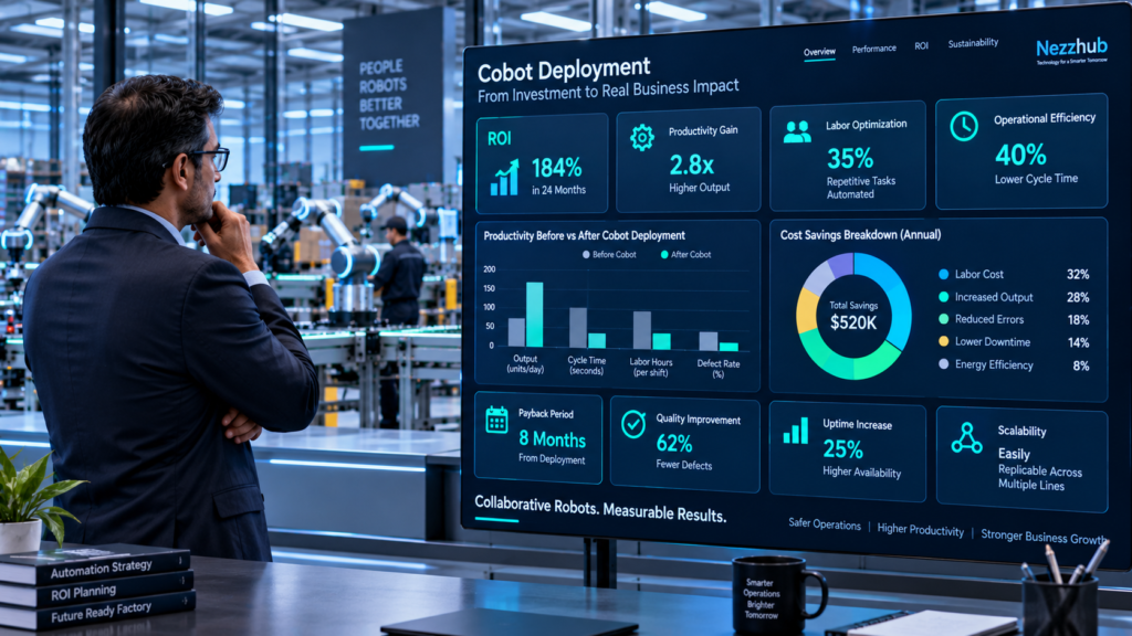
First-Year ROI (%) = [(First-Year Benefit − First-Year Cost) ÷ First-Year Cost] × 100
Compare the automated workcell with the manual baseline over the same first-year period. Count each benefit and cost once. Labor, outsourcing, quality and downtime savings may overlap; include them separately only when they represent distinct economic gains.
Additional contribution should reflect accepted output that can be sold or otherwise used productively. Do not count machine capacity and throughput benefits twice when they describe the same additional output. Keep forecasts separate from measured results.
Payback Period
A simpler procurement measure is:
Payback Months = Initial Deployment Investment ÷ Monthly Verified Net Benefit
This formula gives payback in months only when monthly net benefit is positive and reasonably stable. Monthly net benefit must deduct ongoing operating costs and exclude the upfront investment. Where ramp-up or benefits vary, calculate payback using cumulative cash flows.
But beware of artificially short payback estimates.
Include ramp-up.
Include integration downtime.
Include maintenance.
Include expected changeovers.
Include operator support.
Avoid Automating Cheap Human Flexibility
A worker can recognize a deformed component, rotate it, improvise a grip and continue within seconds.
A robot may require:
vision
new gripper fingers
exception logic
recovery programming
additional sensing
engineering validation
Automation is not economically justified simply because the task is repetitive.
Sometimes human adaptability is the cheaper technology.
A Cobot Can Also Become Conventional Automation
This is commercially important.
A company may buy a collaborative-capable robot and eventually discover that maximum production requires separating people and running the robot faster under an appropriate engineered safety architecture.
That does not mean the purchase failed.
It means the application economics favored separation over continuous collaboration.
The objective is productive automation.
Not ideological commitment to fenceless operation.
RISK MITIGATION & REGULATORY FRAMEWORK
Cobot Safety Must Be Governed at Application Level
ISO 10218-1:2025 and ISO 10218-2:2025 now form the current international industrial robot safety pair, with Part 2 focused specifically on industrial robot applications and cells. ISO also identifies ISO/TS 15066 as complementary guidance for collaborative robot applications.
That makes one governance principle unavoidable:
A certified component does not certify the finished application.
Integration changes risk.
Failure Vector #1 — Tool Hazard
The cobot is power-and-force limited.
The attached tool is sharp.
Mitigation
Assess tool geometry, accessible edges, operating orientation, velocity and credible human contact.
Use guarding or separation where necessary.
Failure Vector #2 — Payload Release
A gripper loses power.
The part falls.
Mitigation
Evaluate retention strategy, gravity, stored energy, safe orientation, vacuum monitoring and failure state.
The robot stopping does not stop a released object.
Failure Vector #3 — Unexpected Restart
A fault clears.
The operator remains inside the work area.
The process resumes unexpectedly.
Mitigation
Engineer restart conditions, operator acknowledgement and safety-state validation.
Recovery logic is part of safety design.
Failure Vector #4 — Safety Configuration Drift
A technician changes:
speed
payload
tool
fixture
workspace
program
The original safety assumptions no longer match production.
Mitigation
Apply configuration control.
Trigger re-assessment for safety-relevant changes.
Record approved parameters.
Failure Vector #5 — Vision or AI Misclassification
Some modern Collaborative Robots use AI-enabled vision for part recognition, pose estimation, inspection or adaptive manipulation.
A model may misclassify an object or behave poorly outside its validated distribution.
Mitigation
Separate AI confidence from safety authority unless the system is specifically engineered and validated for that safety function.
Use deterministic safety functions where appropriate.
NIST AI RMF: Apply It When AI Actually Enters the Cobot Stack
NIST’s AI RMF is voluntary, use-case agnostic and designed to help organizations manage risks across AI design, deployment, use and evaluation. Its Playbook organizes suggested actions around Govern, Map, Measure and Manage.
It should not be forced onto a deterministic cobot simply because the machine is called “smart.”
It becomes relevant when AI components materially influence perception, planning, inspection or operational decisions.
NIST also notes that AI RMF 1.0 is currently being revised.
NIST-Oriented AI/Cobot Checklist
- Identify every AI component in the workcell.
- Document its intended purpose.
- Separate AI functions from safety-rated functions.
- Define acceptable operating conditions.
- Record training/validation data provenance where relevant.
- Test lighting and environmental changes.
- Measure false-positive and false-negative behavior.
- Define confidence thresholds.
- Test out-of-distribution inputs.
- Log model/software versions.
- Control updates.
- Maintain human override.
- Test safe degradation.
- Monitor field performance.
- Revalidate material changes.
This complements robot safety engineering.
It does not replace it.
EU Machinery Regulation: 2027 Matters for Cobot Procurement
The EU Machinery Regulation (EU) 2023/1230 is scheduled to apply from 20 January 2027 under the consolidated EUR-Lex text.
That matters for organizations buying machinery now for European deployment during a multi-year lifecycle.
The regulation also specifically lists safety components with fully or partially self-evolving behavior using machine-learning approaches among Annex I categories.
Procurement teams should therefore distinguish:
ordinary robot control
from
AI influencing process behavior
from
machine-learning functionality performing a safety role.
Those are not equivalent compliance cases.
EU AI Act: Do Not Automatically Call Every Smart Cobot “High-Risk AI”
A robot containing AI is not automatically high-risk merely because it moves near people.
Classification depends on the AI system’s intended purpose and how applicable EU AI Act provisions interact with product-safety legislation.
For Industrial Cobots using AI vision or adaptive functions, conduct a documented applicability assessment rather than assigning a regulatory label from marketing terminology.
The same principle applies in reverse.
Calling a system “robotics software” does not exempt an AI function if its actual intended purpose falls within regulated criteria.
EU Cobot Governance Checklist
- Identify the legal manufacturer and integrator roles.
- Document intended use.
- Document reasonably foreseeable misuse.
- Identify applicable machinery requirements.
- Identify safety-related control functions.
- Determine whether AI/ML affects a safety function.
- Assess AI Act applicability separately.
- Maintain technical documentation.
- Maintain software/configuration versions.
- Document safety validation.
- Control substantial modifications.
- Maintain operator instructions.
- Maintain incident and corrective-action records.
- Reassess when tooling or production conditions change.
Legal compliance should be confirmed for the actual jurisdiction and application.
A generic cobot checklist is not a conformity assessment.
Collaborative Robot Production Promotion Gate
Process
- Business transaction defined.
- Manual baseline measured.
- Cycle-time target defined.
- Part variation characterized.
- Exception frequency measured.
- Quality acceptance defined.
Robot and Tooling
- Payload stack calculated.
- Reach validated.
- EOAT tested.
- Cable routing validated.
- Failure states tested.
- Spare strategy established.
Cobot Safety
- Application risk assessment completed.
- Collaborative mode selected deliberately.
- Speed/force conditions validated.
- Stopping behavior verified.
- Tool hazards assessed.
- Payload hazards assessed.
- Restart behavior tested.
- Emergency stop accessible.
- Safety configuration controlled.
Integration
- PLC handshake tested.
- Machine interlocks tested.
- Vision tested under worst conditions.
- Network failure behavior defined.
- Quality verification integrated.
- Production records captured.
Human-Robot Collaboration
- Operator workflow observed.
- Normal interaction cycle measured.
- Alarm messages understandable.
- Recovery procedure trained.
- Changeover procedure validated.
- Maintenance access assessed.
Commercial
- Full TCO calculated.
- Cost per good unit calculated.
- Throughput benefit measured.
- Quality benefit measured.
- Labor capacity value verified.
- Changeover cost included.
- Downtime included.
- Payback sensitivity tested.
If the cell cannot pass these gates, it is not ready for production.
A successful robot demonstration is not the same as a successful manufacturing system.
Evaluate the Complete Workcell Before Purchase.
Do not begin with a robot catalog.
Begin at the workstation.
Measure the manual cycle.
Record every exception.
Count part variations.
Identify the awkward reaches.
Measure machine waiting.
Quantify scrap.
Document changeovers.
Then decide which portion of the work should become deterministic.
Only after that should you select Collaborative Robots, tooling, vision, safety functions and integration architecture.
Run the pilot with real operators.
Use real parts.
Include the worst variants.
Measure collaborative cycle time rather than empty-cell speed.
Track interventions.
Track safety stops.
Track good output.
Track recovery.
Then calculate:
Cost per Good Unit Before Automation
against
Cost per Good Unit After Automation
That number exposes weak projects quickly.
A well-engineered cobot can become a valuable manufacturing asset because it combines programmable motion with a production architecture designed around human participation.
A poorly engineered cobot becomes an expensive arm waiting for someone to rescue it.
The difference is rarely the color of the robot.
It is the quality of the application engineering.
V. APPENDIX & RESEARCH INTEGRITY
Academic and Primary-Source Reference Index
[1] ISO 10218-1:2025 and ISO 10218-2:2025 — Industrial Robot Safety. The current international safety pair addresses industrial robot design and the integration, commissioning, operation and maintenance of robot applications and cells.
[2] ISO/TS 15066:2016 — Collaborative Robots. Specifies safety requirements for collaborative industrial robot systems and their work environments and supplements ISO 10218 guidance. The specification was confirmed as current following review in 2022.
[3] International Federation of Robotics — Collaborative Robots Position Paper. IFR reported cobots at 10.5% of worldwide industrial robot installations in 2023 and describes hand-guided and tablet-based programming as common accessibility mechanisms.
[4] IFR World Robotics 2025. Records 542,000 industrial robot installations worldwide during 2024, with Asia accounting for 74% of new deployments.
[5] NIST AI Risk Management Framework 1.0. Provides a voluntary, use-case-agnostic framework for organizations managing AI risks; the framework is currently undergoing revision.
[6] EU Regulation 2023/1230 on Machinery. The consolidated regulation applies from 20 January 2027 and contains specific treatment of certain safety components using self-evolving machine-learning approaches.
[7] Current Manufacturer Technical Documentation. ABB GoFa, FANUC CRX, Universal Robots UR20 and KUKA LBR iisy specifications were used only for product-level comparison, not as independent proof of enterprise ROI.
Corporate Editorial Transparency & AI Usage Disclosure
NezzHub Editorial Transparency Statement
This article examines collaborative robot applications, workcell integration, safety considerations and methods for evaluating production costs.
AI-assisted systems may support source organization, comparison, drafting and editorial refinement. Final publication responsibility—including source selection, factual verification, commercial interpretation, corrections and editorial judgment—remains with NezzHub’s human editorial process.
Vendor specifications are explicitly treated as vendor-provided data.
No manufacturer specification is presented as independent proof of productivity, safety, payback or ROI.
Author and Editorial Review
Author: Garikapati Bullivenkaiah
Technology research writer with LL.B., LL.M., M.A., and MBA qualifications. He writes about emerging technologies and their business, governance and legal implications. His multidisciplinary academic background informs his analysis of technology adoption, intellectual property, and organizational risk. His articles explain technical concepts and practical considerations for business owners, IT managers and technology decision-makers. LinkedIn Profile
Reviewed by: Chitikineni Ramadevi — Editor
Chitikineni Ramadevi holds an M.Sc. in Computers from Andhra University and has over 10 years of research experience in technology-related subjects. She reviews NezzHub articles for clarity, factual accuracy, source support and practical relevance.
Published by: NezzHub
Research approach: This article draws on primary sources, technical documentation and relevant industry research. References are provided within the article or its sources section.
Last reviewed: 09-11-2026
Corrections: To report a factual error or outdated information, please contact NezzHub.

Garikapati Bullivenkaiah is a seasoned entrepreneur with a rich multidisciplinary academic foundation—including LL.B., LL.M., M.A., and M.B.A. degrees—that uniquely blend legal insight, managerial acumen, and sociocultural understanding. Driven by vision and integrity, he leads his own enterprise with a strategic mindset informed by rigorous legal training and advanced business education. His strong analytical skills, honed through legal and management disciplines, empower him to navigate complex challenges, mitigate risks, and foster growth in diverse sectors. Committed to delivering value, Garikapati’s entrepreneurial journey is characterized by innovative approaches, ethical leadership, and the ability to convert cross-domain knowledge into practical, client-focused solutions.