






Executive Summary
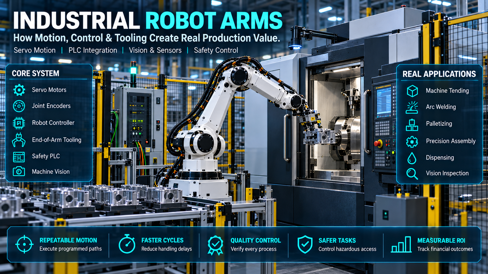
Industrial robot arms create value only when motion, tooling, controls, safety and production data operate as one engineered cell. This Article shows decision-makers how industrial robot arms execute real work, where industrial robotics integration fails, and how to control robot automation cost before a purchase order locks in the wrong architecture.
The arm is rarely the hardest part. The difficult work sits at interfaces: a gripper that cannot tolerate part variation, a PLC handshake that loses state after a fault, a camera that shifts with ambient light, or manufacturing automation software that cannot map robot events to production orders.
Global demand is established, but adoption alone does not prove a business case. The International Federation of Robotics reported about 542,000 industrial robot installations in 2024, with annual installations above 500,000 for the fourth consecutive year.[1]
This paper replaces headline productivity promises with an engineering and financial test. It covers the control loop, coordinate frames, payload and inertia, real application sequences, deployment gates, validation metrics, safety obligations, cyber controls and an auditable return-on-investment model.
The commercial conclusion is direct. Industrial robot arms are justified when a stable process, adequate volume, measurable quality loss and supportable integration plan produce a risk-adjusted payback acceptable to the business—not when a robot demonstration merely looks fast.
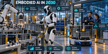
The Future of Embodied AI and Autonomous Robots in 2030
I. The Current Market Landscape and Challenge
Robot Demand Is High; Integration Capacity Is Scarce
Industrial robot arms have become standard production assets rather than experimental equipment. IFR’s 2024 installation mix placed 74% of new deployments in Asia, 16% in Europe and 9% in the Americas, which also shows how unevenly automation capability is distributed.[1]
A buyer does not purchase productive motion by ordering a manipulator. The working asset includes the controller, end effector, fixtures, safety system, upstream and downstream equipment, network interfaces, application code, recovery logic and trained maintainers.
That distinction explains why two factories using the same industrial robot arms can report different outcomes. One cell has controlled part presentation and tested recovery states; the other relies on an operator to clear every dropped part and communication timeout.
The Root Problem Is Process Variability
Robot sales material usually leads with payload, reach and nominal repeatability. Production engineering starts elsewhere: part datum variation, incoming defect rates, lubricant and dust exposure, cable routing, tool wear, changeover frequency and the consequences of a missed grip.
Industrial robot arms repeat programmed motion well, but they do not correct an unstable process unless sensing and control logic explicitly detect the instability. A 0.05 mm repeatability specification cannot compensate for a fixture that moves 1 mm or a stamped part that arrives outside its assumed tolerance stack.
Variation becomes expensive when it reaches the cell without a defined disposition. The robot needs a deterministic decision: continue, retry, reject, request inspection, enter a safe state or call an operator.
Why the Cost of Inaction Is Not Just Labor
The cost of leaving a task manual includes direct labor, overtime, injury exposure, scrap, rework, inspection effort, missed output and the opportunity cost of constrained capacity. Each component must be measured separately because industrial robot arms do not improve all of them automatically.
For example, a welding cell may reduce arc-on variability yet produce no net capacity gain if loading remains the bottleneck. A palletizing cell may remove lifting exposure while adding line stoppages when cartons deform beyond the gripper’s usable range.
The cost of inaction should therefore be compared with the cost of a complete production system. Comparing hourly wages with the arm-only price understates robotic arm deployment expense and overstates the return.
A Decision Baseline Before Vendor Meetings
Document the present process for at least a representative production window. Capture good units per hour, labor content, microstops, planned and unplanned downtime, first-pass yield, scrap, rework, changeover time and safety incidents or near misses.
Then separate fixed demand from forecast demand. Industrial robot arms sized for an optimistic sales forecast can become stranded capital, while systems sized only for today’s mix may require an expensive redesign when the product changes.
The baseline becomes the acceptance contract. If the integrator cannot see how throughput, quality and availability will be measured, the project is not ready for a fixed performance commitment.
Industrial robot arms should enter vendor discussions only after that baseline is approved by operations, quality, maintenance and finance.
II. Deep-Dive Technical Analysis and Evidence
Architecture Overview: The Cell, Not the Arm
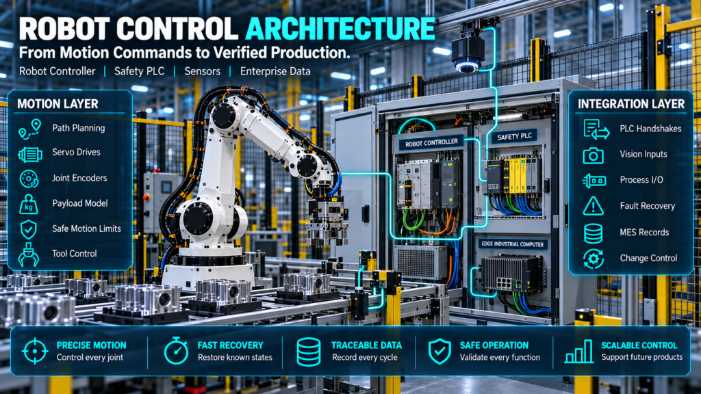
Industrial robot arms are electromechanical manipulators inside a larger control architecture. Their joints deliver motion, but the cell controller determines when motion is allowed, the safety system determines when energy must be limited or removed, and the process equipment determines whether the motion creates a conforming part.
The minimum production architecture contains these layers:
- Manipulator and servo train: links, gearboxes, brakes, motors and joint encoders convert commanded joint positions into physical movement.
- Robot controller: plans trajectories, closes servo loops, evaluates limits, runs application instructions and exposes diagnostic states.
- End-of-arm tooling: grippers, weld guns, spindles, dispensers or inspection sensors create the process outcome.
- Cell PLC: sequences conveyors, machines, clamps, recipes and handshakes beyond the robot controller.
- Safety control: evaluates emergency stops, interlocks, scanners, safe speed and safe position functions through a validated design.
- Perception and process sensing: cameras, force/torque sensors, part-present switches and process instruments reduce uncertainty.
- Enterprise data layer: manufacturing automation software maps production orders, recipes, alarms, quality records and maintenance events.
Removing any layer shifts work elsewhere. Industrial robot arms without reliable fixtures need more vision; cells without event context push troubleshooting into manual log review; cells without defined ownership accumulate undocumented logic changes.
Industrial robot arms therefore belong inside the plant’s controls architecture, asset-management model and change-control process from the concept stage.
How a Command Becomes Motion
A production instruction such as “place component in fixture” is decomposed into targets, orientations, speeds, acceleration limits, blending rules and I/O conditions. The controller transforms the desired tool pose into joint commands through inverse kinematics, then sends current or torque commands to servo drives.
Encoders return joint position. The controller compares commanded and measured state repeatedly, applies its control laws and updates the drive commands while monitoring following error, velocity, torque, collision thresholds and configured limits.
Industrial robot arms do not simply move from point A to point B. The trajectory planner must select a feasible path through joint space while respecting joint limits, wrist configuration, singularities, payload dynamics and obstacles.
Coordinate Frames Are a Production-Control Issue
Robot programs use coordinate frames to express where work exists. Typical frames describe the robot base, tool center point, workpiece, camera, machine and external axes.
A badly calibrated tool frame changes every programmed target. A work frame attached to an inaccurately located fixture makes industrial robot arms repeat the wrong path consistently.
Frame ownership matters during changeover. If a fixture is replaced, the team must know whether to reteach points, update one work-object transform, run a calibration routine or reject the fixture as out of tolerance.
Industrial robot arms become easier to support when frame names, mastering records and calibration procedures follow one documented convention.
Joint, Linear and Circular Motion Have Different Costs
Joint motion is usually the quickest way to move between distant poses because each axis travels toward its target without forcing the tool along a straight Cartesian line. It can create a sweeping tool path, so clearance must be evaluated across the full trajectory.
Linear motion keeps the tool center point on a straight path and is useful for insertion, welding, dispensing and withdrawal. It may drive one joint toward a limit or singularity, reducing speed or causing an infeasible path even when the endpoints look reachable.
Circular motion supports arcs, but path quality depends on programmed geometry, tool calibration and controller behavior. Industrial robot arms need process-specific path validation; a visually smooth simulation is not a dimensional capability study.
Payload Is More Than Kilograms
A payload rating is a boundary, not a selection rule. Engineers must account for the mass of the end effector, adapters, hoses, cables and workpiece, plus the center of gravity and inertia seen at the wrist.
Two tools with equal mass can impose different joint loads when one places that mass farther from the mounting flange. Industrial robot arms may accept the static weight yet violate allowable wrist moments during aggressive acceleration.
The right check uses the manufacturer’s load diagram and application data. Reduce acceleration or redesign the tool when the load case sits near a limit; do not assume a larger payload model fixes fixture compliance, grip stability or process force.
Reach Is a Three-Dimensional Envelope
Published maximum reach describes an outer boundary. It does not guarantee access at the required tool orientation, nor does it remove the inner dead zone near the robot base.
Offline simulation should test every critical pose with the actual tool geometry, dress package and product envelope. Industrial robot arms mounted on risers, rails or inverted structures also require structural and cable-management analysis.
Accuracy, Repeatability and Process Capability
Repeatability describes how closely a robot returns to a taught pose under stated test conditions. Accuracy describes how closely it reaches the commanded absolute pose; the two values are not interchangeable.
ISO 9283 defines performance criteria and related test methods for manipulating industrial robots, and the 1998 edition remained current after its 2021 review.[2] Buyers should request the metric, test conditions and configuration behind any performance claim.
Industrial robot arms can be highly repeatable yet show path error, thermal drift or absolute-position error across the work envelope. Tool deflection, base movement, backlash, payload identification and calibration quality add error outside the published robot number.
For dimensional work, validate the full process. Measure the part result over time, across shifts, after warm-up, at representative payloads and at the least favorable points in the envelope.
Industrial robot arms should be judged by process capability at the product characteristic, not by an isolated brochure number.
Integration Flowchart: From Order to Verified Part
- Receive the production order.
- Select and verify the recipe.
- Confirm machine readiness and the required safety conditions.
- Execute the approved robot task.
- Check the result using process sensors or inspection.
- If accepted, record completion and release the part.
- If rejected, follow the approved retry, rejection or stopping procedure.
- Resume only after the required recovery checks are complete.
The business order becomes a recipe, not a raw motion command. The PLC confirms machine and safety state, industrial robot arms execute controlled paths, sensors validate the outcome, and the cell records a result that can be reconciled with production and quality systems.
Every arrow needs a defined protocol and timeout. A robust handshake includes request, acknowledge, busy, complete, fault and reset states rather than a single “start” bit.
Industrial robot arms also need a defined response when those signals arrive late, out of order or after a controller restart.
Failure Recovery Is Part of the Architecture
A cell that runs only from a clean start is a demonstration. Production code must recover from stopped conveyors, open guards, empty feeders, double picks, lost vacuum, dropped components, rejected welds, camera timeouts, power interruption and upstream starvation.
Industrial robot arms should stop in a state the PLC can interpret. After a restart, the system must determine whether a part is in the tool, whether the machine owns the part, whether process energy is active and which step can be safely repeated.
Recovery screens should guide trained operators without bypassing safeguards. The fastest fault reset is not always the safest or least damaging action.
Real Application 1: Machine Tending
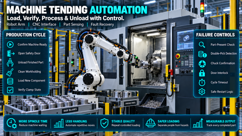
In a machine-tending cycle, the robot receives permission to enter, removes the completed part, manages chips or coolant, loads the next blank, confirms seating, exits the hazard zone and signals the machine to start. The machine door, chuck or clamp and robot state must remain synchronized.
Industrial robot arms fail this application when blanks nest together, chips prevent seating, jaws wear or the cell loses track of part identity. A part-present sensor and clamp confirmation are more valuable than shaving a fraction of a second from free-space travel.
The commercial metric is spindle utilization, not robot utilization. If the machine waits for upstream material or downstream inspection, a faster robot will not improve output.
Real Application 2: Arc Welding
Welding uses coordinated path motion, process triggers, torch orientation, wire feed, voltage and travel speed. Positioners may become coordinated external axes so the weld stays accessible and the joint configuration remains stable.
Industrial robot arms reproduce paths, but fit-up variation can move the seam. Touch sensing, through-arc seam tracking or vision can correct defined errors, while tip wear, spatter, cable drag and thermal distortion still require maintenance and process control.
Quality evidence should include defect rate, rework minutes, destructive or nondestructive test results and parameter traceability. “Consistent welds” is not an acceptance criterion.
Real Application 3: Palletizing
Palletizing looks simple because the path is repetitive, yet the load model changes with layer height and product arrangement. The controller or PLC must track case pattern, pallet presence, slip sheets, gripper zones and recovery after a removed or damaged case.
Industrial robot arms need sufficient vertical reach and wrist capacity at the far corners of the pallet. Vacuum performance changes with corrugated-board porosity, surface damage, dust and altitude, so grip confirmation and controlled drop handling matter.
Measure completed pallets per hour, damaged cases, changeover time and intervention rate. A cell that meets cycle time only with perfect cartons has not passed a representative acceptance test.
Real Application 4: Dispensing and Assembly
Dispensing requires path accuracy, constant standoff, stable speed and synchronization between motion and material flow. Bead width can change with viscosity, temperature, pressure, nozzle wear and start-stop delay even when industrial robot arms follow the same path.
Assembly adds contact physics. Chamfers, compliance devices, force sensing or search routines may be needed because a nominally aligned insertion can jam when tolerances accumulate.
The acceptance plan should inspect the product result, not merely the robot coordinates. Measure bead geometry, insertion force, leak rate, torque signature or another process-specific characteristic.
Real Application 5: Vision-Guided Picking
Vision-guided cells estimate part pose, transform it into the robot frame and select a reachable grasp. Calibration errors, occlusion, reflective surfaces, mixed parts and lighting changes can produce confident but wrong results.
Industrial robot arms need a defined policy for low-confidence detections and unreachable grasps. The application should reject or re-image uncertain cases rather than turning perception uncertainty into collisions.
If machine learning controls a safety-relevant function, governance obligations may change. Conventional deterministic vision used only for quality or pose estimation should not be mislabeled as autonomous AI.
Deployment Challenges That Appear After Purchase
Dress Packs and Cable Fatigue
Hoses and cables change the reachable envelope, add wrist load and fail under repeated bending or abrasion. A simulation without the production dress pack gives false confidence about clearance and service life.
Product Change and Recipe Control
Industrial robot arms can store many programs, but uncontrolled recipes create traceability risk. Versioned code, approved parameters, role-based access and a tested rollback process belong in the operating model.
Environmental Limits
Welding spatter, foundry heat, washdown chemicals, food-contact requirements and explosive atmospheres demand suitable variants and supporting equipment. A standard enclosure rating cannot be extended by assumption.
Obsolescence and Support
Controller hardware, operating systems, fieldbus options and proprietary engineering tools have different support lives. The purchase review should price software licenses, backups, spare parts, training and remote-support arrangements.
Cybersecurity Boundaries
Connecting industrial robot arms to plant and enterprise networks creates an operational-technology attack surface. Remote access, default credentials, unmanaged engineering laptops, unapproved USB devices and flat networks can convert a maintenance convenience into a production risk.
Performance Evaluation Matrix
The matrix below turns commercial promises into acceptance evidence. Targets should be derived from the plant baseline and agreed before final design approval.
| Evaluation dimension | Measurement method | Acceptance evidence | Common distortion |
| Cycle time | Timestamp 30–100 consecutive representative cycles | Median, 95th percentile and maximum cycle time | Reporting one best cycle |
| Availability | Availability (%) = [(Planned Production Time − Attributable Downtime) ÷ Planned Production Time] | Logged faults with ownership and duration | Excluding microstops |
| First-pass yield | Good units without rework divided by total units | Quality-system records by product and shift | Counting reworked units as first-pass good |
| Position performance | ISO 9283-aligned or application-specific test | Defined load, speed, pose and temperature | Quoting repeatability as accuracy |
| Changeover | Last good part A to first approved part B | Timed operator procedure and recipe record | Excluding inspection approval |
| Intervention rate | Manual entries per 1,000 cycles | Reason-coded event history | Treating resets as planned work |
| Energy | Metered cell energy per conforming unit | Production-normalized kWh | Quoting robot-only consumption |
| Safety validation | Documented verification and validation | Test records, signatures and controlled revisions | Treating component certification as cell validation |
| Recovery | Injected representative faults | Successful safe recovery from each state | Testing only emergency stop |
| Data integrity | Reconcile cell count with MES/quality records | Timestamped, traceable production record | Counting commands instead of completed parts |
Industrial robot arms should be accepted against the system matrix, not a single speed or repeatability figure. The matrix also prevents throughput gains from hiding scrap, intervention and energy penalties.
III. Commercial Solutions and Best Practices
Feature and Cost Comparison Table
The examples below represent different heavy industrial use cases, not interchangeable commodities. Specifications come from manufacturers’ current product pages; final values, options and regional availability must be confirmed in a signed quotation.[3][4][5]
| Market solution | Published configuration | Published payload / reach | Notable published detail | Strong-fit applications | Cost treatment |
| FANUC R-2000iD/210FH | Six-axis, floor mount, R-30iB Plus controller | 210 kg / 2,605 mm | ±0.05 mm repeatability; 1,150 kg mechanical weight; 3 kW average power | Spot welding, material handling, machine loading | Quote required; price complete cell, software and service |
| KUKA KR 210 R2700-2 | KR QUANTEC, floor mount, KR C5 or KR C5-2 | 210 kg / 2,701 mm | IP65/IP67 listed on current product page | Handling, foundry variants and process work | Quote required; verify controller, safety and application packages |
| ABB IRB 6790-205/2.80 | Foundry Prime, harsh-environment model | 205 kg / 2,800 mm | IP69; designed for high-pressure washing and 100% humidity | Water-jet cleaning, washing and harsh environments | Quote required; compare lifecycle maintenance and utilities |
This is a shortlist aid, not a ranking. Industrial robot arms should be selected from application load cases, reach studies, environmental requirements, local service capability, installed-base skills and lifecycle commercial terms.
Industrial robot arms with similar payload and reach can still differ materially in software options, service access, energy behavior and plant support coverage.
ABB reports that its IRB 6790 uses 15% less power and can reduce maintenance costs by up to 60% compared with its IRB 6640.[5] Those are manufacturer comparisons for a defined predecessor and must not be generalized to competing cells or assumed in an ROI model without site evidence.
Why Arm-Only Prices Mislead Buyers
The manipulator and controller may be only part of robot automation cost. A complete budget can include end tooling, fixtures, guarding, safety PLCs, scanners, conveyors, vision, process equipment, electrical and pneumatic panels, engineering, simulation, installation, training and production ramp support.
Industrial robot arms also create recurring costs: preventive maintenance, calibration, consumables, software subscriptions, backups, spares, cybersecurity work and specialist call-outs. Financing and tax treatment belong in the business model, but they do not improve technical feasibility.
A credible request for quotation separates assumptions and exclusions. It states product mix, cycle definition, utilities, incoming variation, uptime window, acceptance runs, documentation, source-code access, warranty response and responsibility for upstream and downstream equipment.
The Seven-Gate Robotic Arm Deployment Framework
Gate 1: Process Qualification
Choose a process with measurable demand and controlled inputs. Industrial robot arms are poor first projects when the product design changes weekly or experienced operators rely on undocumented judgment to compensate for unstable materials.
Gate 2: Concept and Reach Validation
Build a digital model with fixtures, tools, service clearances, parts and interference zones. Test every product, approach, withdrawal and recovery pose—not only the nominal cycle.
Gate 3: Risk Assessment
Perform a task-based risk assessment early enough to change the concept. Industrial robot arms, tools, workpieces and process energy all contribute hazards; guarding cannot be sized from the robot brochure alone.
Gate 4: Controls and Data Contract
Define PLC states, safety interfaces, robot variables, recipes, alarm taxonomy and MES or historian records. Manufacturing automation software should consume stable event definitions rather than scraping human-readable alarm screens.
Gate 5: Detailed Design Review
Freeze the payload model, tooling, fixture datums, cable routes, network zones, component list and support plan. Review maintainability by simulating access to service items and likely jam locations.
Gate 6: Factory Acceptance Test
Run industrial robot arms with representative parts, rates and injected faults at the integrator. Record deviations, owners and retest evidence; shipping an unresolved issue converts cheap workshop access into expensive plant downtime.
Gate 7: Site Acceptance and Capability Ramp
Repeat critical tests after installation because foundation, utilities, networks and upstream equipment have changed. Release production only when safety validation, training, backups, spares and performance evidence are complete.
Integration Contract Clauses Worth Buying
Specify deliverables rather than asking for a “turnkey” cell. Industrial robotics integration contracts should include native project files, commented source code, electrical and pneumatic drawings, safety validation records, risk assessment, backup images, passwords transferred through an approved process, spare-parts list and maintenance instructions.
Define software ownership and license portability. Industrial robot arms become costly to modify when the plant cannot open a project, lacks an option license or depends on a single integrator for every recipe change.
Set acceptance around the performance matrix. Include production mix, run duration, planned stops, quality criteria, recoverable fault cases, data reconciliation and rules for retest.
IV. Business Outcomes and Strategic ROI Takeaways
Build ROI From Incremental Cash Flow
An ROI model should compare the future cash flows of the proposed cell with a credible no-project baseline. Count only benefits the plant can capture, such as avoided overtime, reduced scrap purchases, deferred hiring, released capacity with demand, or lower injury-related expense supported by internal evidence.
Industrial robot arms do not create savings merely because labor minutes disappear from one operation. If workers are reassigned, model the productive value of that reassignment or treat the benefit as capacity rather than cash savings.
Use this simple payback equation:
Simple Payback (years) = Installed Capital ÷ (Annual Captured Benefit − Annual Incremental Operating Cost)
Use this screening calculation only when annual net benefit is positive and reasonably stable. Where commissioning, ramp-up or benefits vary substantially, calculate payback using cumulative cash flows.
Simple payback is easy to communicate but ignores the timing of cash flows after payback. For larger robotic arm deployment programs, add net present value, internal rate of return, tax treatment and scenario probabilities.
Worked ROI Scenario—Illustrative, Not an Industry Benchmark
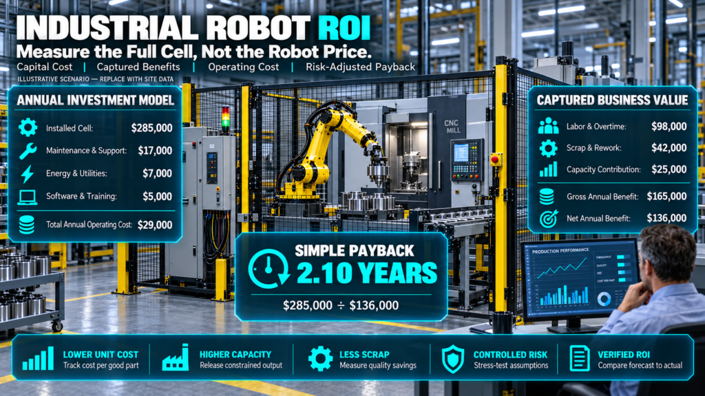
Assume a complete installed cell costs $285,000. The plant expects $98,000 in captured labor and overtime benefit, $42,000 in scrap and rework reduction, and $25,000 in capacity contribution each year, while maintenance, energy, software and support add $29,000 annually.
Annual net benefit is $136,000, so simple payback is about 2.10 years. This result is a worked scenario; it is not evidence that industrial robot arms generally pay back in 2.10 years.
Now stress the assumptions. If captured benefits fall 20% while operating costs remain fixed, annual net benefit falls to $103,000 and payback stretches to about 2.77 years.
If installed capital rises 15% and benefits fall 20%, payback reaches roughly 3.18 years. That sensitivity is more useful to a capital committee than a single optimistic number.
Cost Optimization Without Hollowing Out the Cell
The strongest cost optimization removes complexity at the process level. Standardize part presentation, reduce product variants, reuse approved electrical and software patterns, select common spares and design changeover around repeatable datums.
Cutting safety validation, recovery engineering or operator training lowers the purchase price while increasing lifecycle risk. Industrial robot arms generate value during stable production, so commissioning quality is a financial control.
Consider phased scope when uncertainty is high. A paid proof of concept can validate vision, grip or process feasibility before the business commits to production hardware, but its test conditions must represent the real part distribution.
Industrial robot arms should not advance from proof of concept until the team records pass criteria, failure cases and unresolved scale-up risks.
Outcomes to Report After Go-Live
Report units per scheduled hour, first-pass yield, intervention rate, attributable downtime, changeover time, energy per good unit and maintenance hours. Compare industrial robot arms with the frozen baseline and explain material changes in product mix or demand.
Avoid reporting robot utilization alone. A robot can remain busy making buffer inventory, moving rejected parts or cycling while the constrained operation sits elsewhere.
The first 30, 60 and 90 days should have named owners for recurring losses. A cell that meets the average target but depends on nightly engineering support has not reached operational maturity.
V. Technical Deployment Playbook
Phase A: Observe the Real Work
Film representative cycles with appropriate privacy and safety controls, then code delays and interventions by reason. Interview operators about edge cases because standard work often omits the actions that keep marginal processes running.
Industrial robot arms require explicit logic for those edge cases. If the current process depends on touch, sound or visual judgment, decide whether to add sensing, redesign the product interface or retain human inspection.
Phase B: Specify the Production Contract
Define good-unit output, quality criteria, scheduled time, product mix, input condition and permitted manual work. State whether the cycle includes loading, inspection, labeling, pallet exchange or downstream confirmation.
Set the expected autonomy window. Industrial robot arms that need a person every ten minutes may still improve ergonomics, but the staffing model must reflect that intervention rate.
Phase C: Engineer the Load and Tool
Model worst-case workpiece mass, tool mass, center of gravity, inertia and dynamic motion. Verify grip force across friction variation and consider what happens when power, air or vacuum is lost.
Tooling should include part detection and a predictable release path. Industrial robot arms cannot recover gracefully if the system cannot tell whether the tool is empty, holding one part or holding two.
Phase D: Design Safety and Operations Together
Map every human task: loading, clearing faults, changing tools, cleaning, teaching, maintaining and recovering after power loss. Each operating mode needs defined access conditions, speed or energy limits where applicable, and a validated stop response.
Do not treat perimeter guarding as the complete safety design. Industrial robot arms may carry sharp, hot or heavy parts, and the application can introduce hazards absent from the manipulator.
Phase E: Prove the Control States
Test cold start, normal stop, emergency stop, guard opening, communication loss, sensor disagreement, empty supply, full reject bin and power restoration. Confirm which controller owns each transition and how duplicate commands are prevented.
Industrial robotics integration should favor explicit state machines over scattered interlocks. A readable state model shortens debugging and makes later changes safer.
Phase F: Instrument From Day One
Log cycle start and completion, recipe, product ID when applicable, fault code, recovery time, quality result and maintenance event. Synchronize clocks or timestamps will not support root-cause analysis.
Manufacturing automation software should store enough context to separate robot, tooling, machine, material and upstream losses. Sending every low-level servo event to cloud storage creates cost without necessarily creating insight.
Phase G: Transfer Capability to the Plant
Train operators on normal recovery, technicians on controls and safety diagnostics, engineers on backups and change control, and managers on performance interpretation. Industrial robot arms should not depend on undocumented knowledge held by one commissioning engineer.
Keep tested offline backups of controllers, PLCs, safety programs, vision jobs and recipes. Record firmware and option versions because a file alone may not recreate the running system.
VI. Evidence and Validation
Academic and Engineering Evidence
Industrial robot path planning is a constrained optimization problem, not a drag-and-drop animation. A 2023 paper on collision-free routing and scheduling used an industrial stud-welding case to examine the combined challenge of cycle-time minimization and collision avoidance in multi-robot stations.[6]
Research on time-optimal path tracking also warns that mismatch between the robot model and physical plant can create torque errors and infeasible trajectories.[7] The practical implication is to validate optimized cycles on production hardware with the real payload.
A separate real-robot study used reinforcement learning to improve trajectory tracking of a flexible-joint manipulator and reported learning in under two hours for its experimental setup.[8] That result is promising research evidence, not a universal performance percentage for commercial industrial robot arms.
Claim Validation Rules
Every percentage should name its baseline, population, measurement window and source. Manufacturer comparisons can support product-specific decisions but should not be rewritten as market-wide facts.
Every robot specification should identify the exact variant. Industrial robot arms within one family can differ in reach, payload, mounting position, protection class, repeatability and controller compatibility.
Every financial claim should state whether it is historical, forecast or illustrative. ROI forecasts need sensitivity ranges because demand, labor capture, ramp time and maintenance are uncertain.
Every safety claim should describe the integrated application. Certification or conformity of an individual component does not prove that the completed cell is safe.
VII. Risk Mitigation and Regulatory Framework
Safety Standards and Legal Scope
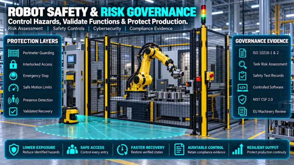
ISO 10218-1:2025 addresses safety requirements for industrial robots, while ISO 10218-2:2025 addresses industrial robot applications and robot cells.[9][10] The applicable legal duties still depend on jurisdiction, machinery scope and the party placing the system into service or on the market.
Industrial robot arms should receive an application-level risk assessment and documented verification and validation. The process must cover foreseeable use, misuse, maintenance, teaching, fault recovery and interactions with connected machines.
The EU Machinery Regulation (EU) 2023/1230 applies from 20 January 2027 and explicitly addresses machinery incorporating fully or partially self-evolving behavior using machine-learning approaches.[11] Organizations deploying into the EU should assess transition obligations with qualified legal and conformity specialists.
The EU AI Act does not make every robot a high-risk AI system. Its Article 6 conditions include cases where AI is a safety component of a product covered by listed Union harmonization legislation and that product requires third-party conformity assessment.[12]
Safety Compliance Checklist
- Define the machine boundary, intended use, foreseeable misuse and lifecycle tasks.
- Complete and approve a task-based risk assessment before detailed design freeze.
- Calculate and validate protective measures, including stopping performance where relevant.
- Verify safety-related control functions across normal, setup, maintenance and recovery modes.
- Validate tooling hazards, retained energy, workpiece ejection and process-specific energy.
- Control changes to robot, PLC, safety, vision and recipe programs.
- Retain test records, drawings, manuals, declarations and training evidence.
- Reassess the cell after material changes to tooling, speed, payload, layout or software.
Industrial robot arms must not be declared safe solely because they operate within fences. The entire cell needs evidence that protective measures reduce identified risks to an acceptable level under the applicable framework.
Cybersecurity and Network Governance
NIST Cybersecurity Framework 2.0 provides outcome-based guidance for governing and managing cybersecurity risk without prescribing one implementation.[13] NIST’s draft CSF 2.0 Manufacturing Profile maps that approach to manufacturing and operational-technology environments.[14]
Apply the framework proportionately. Industrial robot arms on isolated cells still require controlled engineering access and backups, while connected fleets may require segmentation, centralized identity, monitored remote support and formal vulnerability handling.
OT Cybersecurity Checklist
- Inventory controller, PLC, safety, vision, HMI, switch and engineering-station assets.
- Record firmware, software options, licenses, support status and network dependencies.
- Remove or control default accounts; assign named roles and review privileged access.
- Segment the cell from enterprise and internet-facing networks with approved conduits.
- Require managed, time-limited remote access with logging and explicit plant authorization.
- Test backups and restoration in a controlled environment.
- Review vendor advisories and patch or mitigate according to production and safety risk.
- Monitor configuration changes and failed authentication without flooding operations teams.
- Include cyber loss of view or control in incident response and safe-state procedures.
Do not patch a production controller blindly. Industrial robot arms require coordinated cyber and process-safety decisions because an update can change communications, motion behavior, option compatibility or validated configurations.
AI and Vision Governance
NIST’s AI Risk Management Framework is voluntary guidance for managing risks to individuals, organizations and society.[15] Use it when perception or adaptive models materially affect robot decisions; deterministic motion programs do not need an AI label to sound advanced.
For AI-enabled industrial robot arms, document training-data scope, test distributions, confidence thresholds, fallback behavior, drift monitoring, human override and responsibility for model updates. Safety functions should not depend on an unvalidated inference path.
Final Go/No-Go Governance Test
Approve the project only when technical feasibility, risk controls, lifecycle ownership and risk-adjusted economics are all supported. A fast simulated cycle cannot compensate for missing safety evidence, unstable inputs or an unsupported controller architecture.
Industrial robot arms require the same capital governance as other production equipment, plus explicit controls for software, safety logic and connected-system risk.
Industrial robot arms should enter production with named owners for operations, maintenance, controls, safety, cybersecurity and performance reporting. If ownership is unclear before handover, it will be expensive after warranty support ends.
Request a Deployment-Readiness Assessment
Before requesting final quotes, assemble the baseline, part samples, layout, utility constraints, target cycle, quality criteria, product roadmap and required production interfaces. Ask shortlisted integrators to return a common compliance matrix so technical and commercial differences remain visible.
A disciplined assessment can determine whether industrial robot arms are the correct investment, whether the process needs redesign first, and which risks belong in the contract. The next useful step is an evidence-based concept review—not a generic product demonstration.
VIII. Frequently Asked Commercial Questions
How do industrial robot arms know where to move?
The controller converts a programmed tool pose and motion type into joint trajectories, then uses encoder feedback to control each servo axis. Work frames, tool calibration, kinematic configuration and limits determine whether the commanded pose is reachable and useful.
Are industrial robot arms accurate to their repeatability specification?
Not necessarily. Repeatability is return-to-pose performance under defined conditions, while accuracy is closeness to the commanded absolute pose; fixtures, tools, payload, temperature and calibration affect the finished process.
What normally drives robot automation cost?
The major drivers are application engineering, end tooling, fixtures, safety, material presentation, process equipment, controls, vision, installation and validation. Complex part variation and recovery logic can cost more than expected even when industrial robot arms are standard models.
Can one robot run several products?
Yes, if the reach, load, tooling, fixtures, sensing and cycle time support every variant. Recipe governance and changeover validation are essential because storing several programs does not prove flexible production.
Do industrial robot arms run continuously without people?
They can execute repeated cycles for long periods, but material replenishment, consumables, tool wear, inspection, maintenance and exception recovery still require an operating model. The honest metric is intervention rate over a defined production window.
Should a buyer choose the robot brand before the integrator?
Local support and plant standards matter, but application engineering usually dominates the outcome. Shortlist compatible industrial robot arms while evaluating the integrator’s process knowledge, safety capability, recovery design and source-code handover.
When is machine vision worth the added complexity?
Vision is justified when it controls enough position or quality variation to produce measurable value. If a low-cost fixture can locate the part more reliably, mechanical error-proofing may reduce lifecycle support and compute overhead.
How should industrial robotics integration connect to MES or ERP?
Use the cell PLC or an approved edge layer to expose controlled production states and records. Avoid letting enterprise systems send unrestricted motion commands directly to industrial robot arms.
How long does robotic arm deployment take?
Duration depends on process maturity, custom tooling, safety design, component lead times, validation and plant shutdown access. A vendor should provide a gated schedule with owner, evidence and exit criteria for every phase.
What should an executive dashboard show?
Show good output per scheduled hour, first-pass yield, downtime by owner, intervention rate, changeover, maintenance effort, energy per good unit and captured financial benefit. Robot motion hours alone do not establish value.
IX. Appendix and Research Integrity
Sources and Citations Index
- International Federation of Robotics, World Robotics 2025—Industrial Robots, Executive Summary, installation totals and regional shares for 2024: https://ifr.org/img/worldrobotics/Executive_Summary_WR_2025_Industrial_Robots.pdf.
- International Organization for Standardization, ISO 9283:1998—Manipulating industrial robots: Performance criteria and related test methods: https://www.iso.org/standard/22244.html.
- FANUC America, R-2000iD/210FH product specifications: https://www.fanucamerica.com/products/robot/r-2000id-210fh.
- KUKA, KR QUANTEC product family and KR 210 R2700-2 specifications: https://www.kuka.com/en-gb/products/robotics-system/industrial-robots/kr-quantec.
- ABB, IRB 6790 product specifications and manufacturer comparisons: https://www.abb.com/global/en/areas/robotics/products/robots/articulated-robots/large-robots/irb-6790.
- Spensieri et al., An Iterative Approach for Collision Free Routing and Scheduling in Multirobot Stations, arXiv:2309.01149, 2023: https://arxiv.org/abs/2309.01149.
- Palleschi et al., Time-Optimal Path Tracking for Industrial Robots: A Model Predictive Control Approach, arXiv:1907.01348, 2019: https://arxiv.org/abs/1907.01348.
- Dmytro Pavlichenko and Sven Behnke, “Real-Robot Deep Reinforcement Learning: Improving Trajectory Tracking of Flexible-Joint Manipulator with Reference Correction,” 2022, arXiv:2203.07051. https://arxiv.org/abs/2203.07051
Standards, Regulation and Governance Sources
- International Organization for Standardization, ISO 10218-1:2025—Robotics: Safety requirements, Part 1, Industrial robots: https://www.iso.org/search.html?q=ISO%2010218-1%3A2025.
- International Organization for Standardization, ISO 10218-2:2025—Robotics: Safety requirements, Part 2, Industrial robot applications and robot cells: https://www.iso.org/search.html?q=ISO%2010218-2%3A2025.
- European Union, Regulation (EU) 2023/1230 on machinery: https://eur-lex.europa.eu/eli/reg/2023/1230/oj.
- European Union, Regulation (EU) 2024/1689, Artificial Intelligence Act: https://eur-lex.europa.eu/eli/reg/2024/1689/oj.
- National Institute of Standards and Technology, Cybersecurity Framework 2.0, NIST CSWP 29, 2024: https://doi.org/10.6028/NIST.CSWP.29.
- National Institute of Standards and Technology, Cybersecurity Framework 2.0 Manufacturing Profile, NIST IR 8183 Rev. 2 Initial Public Draft, 2025: https://doi.org/10.6028/NIST.IR.8183r2.ipd.
- National Institute of Standards and Technology, AI Risk Management Framework: https://www.nist.gov/itl/ai-risk-management-framework.
Research Method and Limitations
This Article prioritizes standards bodies, regulators, government technical guidance, manufacturer product pages and identifiable academic papers. Product specifications and regulatory requirements can change. Confirm the applicable version and configuration before making a procurement decision.
The comparison table does not include invented list prices because industrial systems are configured and quoted by region, options and scope. ROI values are explicitly illustrative and must be replaced with site measurements for an investment decision.
No source in this paper establishes a universal productivity, payback, uptime or defect-reduction percentage for industrial robot arms. Outcomes depend on process stability, cell design, validation, staffing and operating discipline.
Corporate Editorial Transparency and AI Usage Disclosure
AI-assisted tools were used to support research organization, drafting and language refinement. NezzHub retains editorial responsibility for the published article. Vendor inclusion does not constitute endorsement.
Author and Editorial Review
Author: Garikapati Bullivenkaiah
Technology research writer with LL.B., LL.M., M.A., and MBA qualifications. He writes about emerging technologies and their business, governance and legal implications. His multidisciplinary academic background informs his analysis of technology adoption, intellectual property, and organizational risk. His articles explain technical concepts and practical considerations for business owners, IT managers and technology decision-makers. LinkedIn Profile
Reviewed by: Chitikineni Ramadevi — Editor
Chitikineni Ramadevi holds an M.Sc. in Computers from Andhra University and has over 10 years of research experience in technology-related subjects. She reviews NezzHub articles for clarity, factual accuracy, source support and practical relevance.
Published by: NezzHub
Research approach: This article draws on primary sources, technical documentation and relevant industry research. References are provided within the article or its sources section.
Last reviewed: 09-12-2026
Corrections: To report a factual error or outdated information, please contact NezzHub.

Garikapati Bullivenkaiah is a seasoned entrepreneur with a rich multidisciplinary academic foundation—including LL.B., LL.M., M.A., and M.B.A. degrees—that uniquely blend legal insight, managerial acumen, and sociocultural understanding. Driven by vision and integrity, he leads his own enterprise with a strategic mindset informed by rigorous legal training and advanced business education. His strong analytical skills, honed through legal and management disciplines, empower him to navigate complex challenges, mitigate risks, and foster growth in diverse sectors. Committed to delivering value, Garikapati’s entrepreneurial journey is characterized by innovative approaches, ethical leadership, and the ability to convert cross-domain knowledge into practical, client-focused solutions.